Sunday, December 2, 2012

KitchenAid & Kitchen Damage

This summer we decided to remodel our kitchen. It is an intricate process, involving a contractor, an interior designer, builders, plumbers, electricians, tilers, cabinet installers, counter top installers, appliance installers and flooring layers. Inspectors must approve vital steps along the way. I developed deep respect for the contractor who forged this orchestra into a coherent ensemble.

The work was finished on time, taking roughly ten weeks. I must warn you that it takes adjustment to live without a proper kitchen for such extended time. Preparing meals for four on one hot plate can be taxing. I recommend an electric induction cooktop like the DUXTOP 1800-Watt Portable Induction Cooktop Countertop Burner 8100MC for cast-iron ware, but must admit that plenty pizza was ordered.

The work was finally finished. The day came to test the appliances. We use our old refrigerator and gas range. Their activation was uneventful. The new dish washer and microwave oven posed no problem either. However, when the brand new built-in KitchenAid® Dual-Fan Convection Oven with Steam-Assist Technology (KEBU107SSS) was energized, trouble began. The high-end appliance is set into a large opening of one of the wonderful-looking wood-finish Merillat cabinets at upper body level. It needs a particular high amperage power line and a hose for filtered water. Immediately on activation, the oven's control panel displayed the error message:

F7-E2: Boiler NTC out of range.

The service center was consulted. The following week a subcontracted technician paid us a visit, connected his computer to the oven, checked its vital signs, and ordered one W10076760 sensor, one 9758598 boiler and one W10160958 cntrl-elec, worth roughly 450 dollars in toto, on warranty. The parts arrived on the door step two days later. On the third day, two other gentlemen arrived to install them and recheck the ovenly functions. The steam function seemed to work at 500° F.

Hooray, the great gadget finally seemed to work as it was supposed to without fail! Of course, the technicians did not bake anything in it. The first uses for the brand-new oven were merrily planned for the next day.

But fate had something else in store. Before we started cooking with the oven, I stepped down into our basement to retrieve the Christmas ornaments, only to find a small puddle of water on the floor encroaching on the cardboard boxes. First I thought our hot water boiler sprung a leak. But no, the water dribbled from above, exactly from the spot where the steam oven is located.

I ran upstairs, opened the doors of the cabinet beneath the oven. The pots and pans stored on the shelves were filled with water and had overflowed. Water was dripping from above. The laminated shelving was already crumbling. The wooden flooring in front of the cabinet showed signs of warping.

In the back, I saw the coupling between the water supply line and the oven line. I saw no drops of water on the tubing. I touched the coupling. It was dry.

No doubt, the water dribbled from the oven above. We could not see precisely where the source was, because a board blocks the view on the oven's underside.

I turned off the water supply. We removed the pots and pans, soaked up the water with rags, and called the service center.

The lady from the other side of the globe was friendly. After she verified our coordinates, I explained what happened. She told me that the next appointment with a service technician was available in eight days. I replied that this was no case for a service technician, but for an adjuster to strike up a damage report.

After a little silence, the sweet voice suggested a service technician one more time. I did not dare turn down her offer in the hope that somebody would show up in the flesh eventually. Furthermore, I asked her to kindly inform her superviser of the water damage to the kitchen.

One day later, we have yet to hear from the superviser. In my opinion, our KitchenAid® steam oven is deeply flawed. It was supposed to be a brand-new, high-end appliance and should have worked right out of the box. Sadly, it never ran properly even after massive repairs. Moreover, it severely damaged a brand-new kitchen cabinet.

It is beyond my expertise to judge whether the manufacturer or the service company are responsible for the damage. Regardless in what fashion this journey will end, the consumer experience has been catastrophic from the beginning. I wonder how the KitchenAid® brand manages to survive against its competitors with such abysmal record.

Addenda
  • A team of experts has visited our home to investigate the cause of the accident. The installation guide for the oven suggests copper tubing for the water supply. The gentlemen divined that the coupling between the copper tubing and the oven had sprung the leak, when the service technicians moved the oven back into the cabinet after the repair. This may happen, I was told, because the copper tubing is stiff and prone to kink. The gentlemen also noted that the technicians had installed only one of the three spare parts that were ordered (12/21/2012).
  • Two days ago, the kitchen cabinet furnisher delivered a replacement for the damaged cabinet housing the steam oven and a new appliance. The company had both installed yesterday. An expert was called in to connect the water line. Another shut-off valve was placed beneath the oven between the piece of copper tubing connected to the oven and the plastic tubing connected to the water filter. This morning, I checked the cabinet beneath the oven for traces of water and was happy not to find any. This afternoon, we tested the new oven's steam function, baking French bread. The oven was preheated to 450° F. The steam function was activated, and the loaves were placed on the rack. The convection fans in the oven's back spun with unbearable noise. The first oven's fans ran quietly during the technician's brief test. Despite, the oven kept working without error messages. The bread rose. Its crust turned nicely brown. About 15 minutes into the process, when the bread was almost ready, the oven stopped with the warning:
    F7-E0: Water is not high enough.
    We checked the cabinet beneath the oven. Plenty water was dribbling from above, accumulating on the shelves. We closed the new shut-off valve and mopped up the spill as much as possible. The bread turned out great (12/29/2012).
  • Today experts visited us to look after the new oven. They attested that electrical wiring behind the convection fans supplying a water level gauge was improperly fastened, allowing one wire to rub against the spinning fans. The rubbing had caused the noise we heard. Once the wire's insulation had been shaven away, the water level gauge failed. The gauge failure apparently allowed the feedwater to flow uncontrolled, spilling into the cabinet below. Because we noticed the leak immediately and shut off the water supply, no water damage to the cabinet could be found this time. The experts repaired the faulty gauge and tested the oven at 300° F for 20 minutes. No malfunction occurred. Regardless of this progress, two brand-new defective ovens in a row provide disconcerting evidence that KitchenAid® needs to urgently improve quality control. Whoever assembled and tested these ovens should feel profoundly embarrassed for their shoddy workmanship (01/10/2013)!
  • We have been baking delicious breads four times to date.
    The appliance performed well, though a relay seems to stick on occasion, producing a soft vibratory sound. No further leaks sprang up. Other than an urgent review of quality control, I may suggest two additional safety features that may help avoid water leaks. First an expansion joint between the oven pipe and the feedwater pipe may help prevent the coupling between the two pipes from leaking because of potential unequal metal expansion owing to differing temperatures at the terminations. Moreover, an external solenoid-operated stop-check valve should be installed in the feedwater line. The valve ought to fail close on power loss or on error signals from the oven's control board (01/20/2013).
  • Recently, we had another kitchen appliance-related experience of note. When we bought the steam-assist oven, we also purchased a kitchenaid gas range with a double oven. After the range broke on average once a year because the igniters, the convection fan and the emergency gas shutoff valve failed, we decided to go for a Bosch model from a nationwide retailer that contracts out delivery and installation to different contractors. Delivery took a week. The installer did not arrive for three weeks. When we complained to the retailer in person, the installer played cat and mouse with us. After four weeks we returned the uninstalled appliance at full refund. We bought the same model at a different store, where delivery and installation are carried out by the same company on the same day within five business days at half the cost. Buyer beware! Some retailers have implemented better business models than others (06/25/2016).

Friday, September 28, 2012

Fukushima Daiichi Nuclear Power Station Unit 1: Blunt Force Impact Damage Inside Primary Containment

The Mar. 11, 2011, Tohoku-Chihou-Taiheiyou-Oki Earthquake and Tsunami precipitated losses of coolant and fuel meltdowns in three reactors at Fukushima Daiichi Nuclear Power Station. Unit 1 was the station's first to incur a meltdown.

Yesterday, the nuclear power station's operator Tokyo Electric Power Co. (TEPCO) released a video of the first endoscopic exploration inside Unit 1's primary containment vessel (PCV) (TEPCO press release with the title "Punching an Access Hole at the Penetration (X100B Penetration) of Unit 1 PCV at Fukushima Daiichi Nuclear Power Station", dated Sep. 27, 2012). TEPCO's video can be downloaded here. General Electric's Mark I primary containment systems are composed of a pear-shaped drywell housing the reactor pressure vessel (RPV) and a doughnut-shaped, water-filled suppression chamber, also known as wetwell. TEPCO's video below explores the inside of the drywell (courtesy: SimplyInfo.org).


Note that the upper part of the drywell is filled with dense steam. Water must be boiling at the bottom of the primary containment.

Furthermore, the dominant color of the drywell's inner surface is grimy black and not brown as observed in Unit 2 (see the video in my post with the title "Fukushima: Fuel Meltdowns & Cold Shutdown" published online Feb. 15, 2012), indicating combustion either by explosion or fire.

18:05 minutes into the video blunt force impact on the drywell becomes visible. A large piece of sharp-edged debris can be seen deposited adjacent to exposed rebar of a reinforced concrete wall structure. The impact suggests that the location was struck by a heavy object, perhaps the object nearby, either falling from above or projected against the drywell wall like a missile.

A high-pressure steam jet exiting from a small RPV breach, also known as small breach Loss of Cooling Accident (LOCA), could have blasted chunks off the RPV or its piping, turning the chunks into projectiles that impacted the drywell.
Addendum
  • During the past week, TEPCO undertook another video camera foray into the primary containment vessel (PCV) of Unit 1 (TEPCO's press handout with the title "Investigation Results of the Inside of Unit 1 PCV at Fukushima Daiichi Nuclear Power Station" dated Oct. 15, 2012). The company released three videos of the exploration.
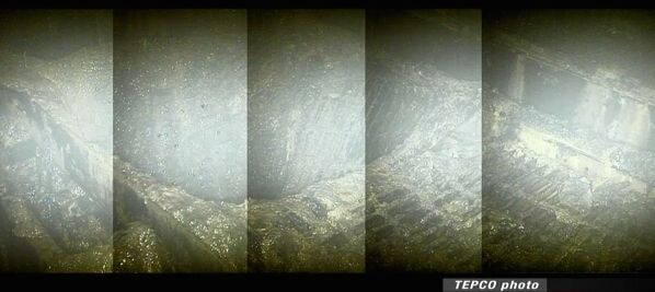
    The two pictures below, courtesy of Simplyinfo.org, were captured between 37 and 44 minutes in the hour-long video.


    The pictures show three types of damage: • the PCV floor fractured (first picture; top left corner), • scattered metal shards (both pictures), suggesting piping shattered in a blast caused by excess interior pressure, and • extreme force impact fragmented large structures and components (bottom picture)(10/17/2012).

Thursday, September 20, 2012

Virtualization & The Mind

In previous posts published Apr. 7 and Nov. 25, 2009, I discussed the use of QEMU for emulating virtual computers and the use VirtualBox to run Google's Chrome OS on an Apple MacIntosh Mini computer, respectively. This post provides more detail on the installation of guest operating systems on two platforms using VirtualBox. VirtualBox is an emulation application originally developed at Sun Microsystems and now supported by Oracle. It permits us to operate a guest operating system (OS) on virtual computers installed on a different platform. Two configurations are discussed (see table below).

Configuration Host Computer Host OS Guest OS
1 Apple MacBook 10.6 Windows 8
2 Dell Inspiron Windows 7 Linux


The two test configurations (table courtesy: HTML Tables).

One configuration entails running a Linux-operated virtual computer on a Microsoft Corporation's Windows 7 (32-bit) operated Dell Inspiron 1318 laptop (2.00 GHz Intel Core 2 Duo; 2 GB RAM). In the other, a Microsoft Windows 8 (64-bit) operated virtual computer is run on a OS X (10.6.8) operated Apple MacBook (2.26 GHz Intel Core 2 Duo; 2 GB RAM). In both examples, the results have been excellent. The virtual guest machines operate astoundingly fast, while the impact on the host computers performance is acceptably small. Below, find suggestions how to proceed with the installation:
  1. Download and install the latest version of the VirtualBox platform package (here 4.2) for each actual computer from Download VirtualBox.
  2. Open the application. The VirtualBox Manager will prompt you to set up a new virtual machine, presenting default options on the right. Set base memory to not more than a third of the host computer's RAM. The base memory can be ramped up to one half of the host computer's RAM. However, this may slow the computer.
  3. Set the virtual machine's video memory to 128 MB.
  4. I chose VMDK as the virtual machine's hard drive format and an 8 GB, expandable, as hard drive size for Linux and 20 GB, fixed, for Windows.
  5. Install guest operating system on the virtual machine. I chose Windows 8 (64 bit) for the OSX-10.6 MacBook host and Crunchbang Linux 10 (32 bit, i-386), a small footprint Ubuntu Linux distribution, for the Windows-7 Inspiron host. You can either install the guest operating systems from disk or iso-images that must be attached to the CD/DVD ROM drive of the virtual machine using 'Devices☞CD/DVD Devices' on VitualBox's pulldown menu.
  6. USB-2.0 support. To enable USB-2.0 devices on the virtual machines, download the Oracle VM VirtualBox Extension Pack for the version matching that of the VirtualBox on your computer from VirtualBox's download page and install the package following conventional host OS-specific procedures.
  7. File sharing. To enable file sharing on the virtual machine, VBoxGuestAdditions need to be installed. If you pull down the 'Device' option on the VirtualBox menu and select 'Shared Folders', a VBoxGuestAdditions iso-disk image containing the necessary files should mount. Eventually, the path to the shared folder on the host must be added to the 'shared Folders' list (see details below). If the VBoxGuestAdditions iso-image does not mount, download the image from the VirtualBox repository and mount it on the virtual CD/DVD-ROM drive, using the VirtualBox pulldown menu option 'Devices☞CD/DVD Devices'.
  8. For Windows guests, open the VBoxGuestAdditions iso-disk image folder in the guest with Windows Explorer and simply run the VirtualBox additions executable that matches the guest's operating system. For Linux guests, install the Linux-headers development packages for the kernel of your guest operating system before you proceed. Crunchbang has been developed as a Debian-based Ubuntu distribution. The needed header packages can be added to the operating system with the Synaptic Package Manager. After the packages have been installed, mount the VBoxGuestAdditions iso-image on the virtual CD/DVD-ROM drive, using the VirtualBox pulldown menu option 'Devices☞CD/DVD Devices'and, using the guest's command line terminal, go to the disk image folder, typing at the prompt:

    cd /media/cdrom

    To install the needed additions on the guest enter on the command line:

    sudo sh ./VBoxLinuxAdditions.run

    After providing your root password, the additions should compile and install. Without Linux headers installed, the script attempts to add a pre-compiled module. In my attempts, the module failed to be added on reboot. Hence, I took the alternative route via compilation. The compiler, however, depends on the Linux-headers development packages. Reboot the guest!
  9. The file sharing path for Linux guests. If shutdown and reboot of the guest proceeded without fail, create a folder in your home directory on the Linux guest as mount point for the folder to be shared on the Windows host. On the Windows host, I created a shared file folder with the name 'share' in the Documents folder, and added the folder's path to the list under the VirtualBox pulldown menu option 'Devices☞Shared Folders':

    C:\Users\Username\Documents\share

    If the correct path is inserted, the ok-button will light blue. Press okay. After that, the folder can be mounted on the Linux guest filesystem just so:

    sudo mount -t vboxsf share /home/Username/Documents/share

  10. The file sharing path for Windows guests. For the Windows guest running on a OS X host, make sure that file sharing is activated under 'System Preferences☞Internet & Wireless☞Sharing' on the host. I made a shared folder with the name 'share' in my documents folder on the host and entered its path in the folder list under the VirtualBox pulldown menu option 'Devices☞Shared Folders':

    /Users/Username/Documents/share

    If the correct path is inserted, the ok-button will light blue. Press okay. On the guest, go to 'Windows Explorer☞Networks☞Map network drive,' select a drive, and add under 'Folder':

    \\vboxsvr\share

    Check 'Connect using different credentials', which will present a login window for the host, asking for your username and password. After providing the correct answers, the shared folder on the host should pop up in the guest's Windows Explorer.
Configuration 1: Windows on OS X.

Configuration 2: Linux on Windows.
I have refrained from exploring the Drag-and-Drop option. But in essence, we are all set to go!

Related Posts


Sunday, July 1, 2012

Fukushima: Station Black Out & Delusion

According to a Japan Times editorial with the title "Nuclear power plant collusion" published online Jun. 23, 2012, industry and government experts appointed by the Japanese Nuclear Safety Commission in 1991 to revise safety standards for station blackouts (SBO) concluded in 1993
“that even if an SBO occurs, it would not lead to a severe accident."
Last year's nuclear reactor disaster at Fukushima Dai-ichi Nuclear Power Station (NPS) in the wake of the great Tohoku-Chihou-Taiheiyou-Oki Earthquake and Tsunami can be considered a station blackout that developed into a severe nuclear accident.

According to Cook and others (1981), “a station blackout is defined as the complete loss of all AC (alternating current, ed.) electrical power to the essential and nonessential switchgear buses in a nuclear power plant.” The authors examined a hypothetical station blackout (SBO) and its consequences, using the boiling water reactor (BWR) at Brown's Ferry NPS Unit 1 as model. The unit produces 1152 MW electrical power, and its design resembles closely that of units 1 - 4 at Fukushima Dai-ichi NPS, except Unit 1 at Fukushima was not equipped with an automatic depressurization system and had an isolation condenser instead of a reactor core isolation cooling (RCIC) system. The description of events at Fukushima Dai-ichi NPS on the day of the earthquake provided in this essay is based on the information the station's operator Tokyo Electric Power Company (TEPCO) has released since the accident.

In the study of Cook and others (1981), the loss of offsite AC power trips the main turbine, scrams the reactor, and the emergency diesel generators fail. Battery-supplied DC power continues to support emergency shutdown systems and components important to reactor safety. The authors explore with models various possible event paths after the batteries are exhausted. Though ground motion rather than a loss of power scrammed the reactors at Fukushima Dai-ichi NPS automatically, the authors' predictions on the worst accident progression converge on the chain of events at Fukushima after 4 p.m. on Mar. 11, 2011. Below, Unit 1 at Fukushima Dai-ichi NPS is used as example.

Systems, Structures, and Components Important to Safety
In conjunction with a high pressure coolant injection (HPCI) system, with which all reactors at Fukushima Dai-ichi as well as at Brown's Ferry are outfitted, RCIC system and isolation condenser constitute crucial components designed to keep the nuclear fuel in the reactor pressure vessel (RPV) covered with water, when the electrical power-generating turbine trips, the main steam isolation valves close, and the reactor scrams. HPCI and RCIC system are described in detail in the appendix of the study of Cook and others (1981).

In a scram, all safety control rods are inserted into the fuel core, instantly disrupting the nuclear chain reaction. The closing of the main steam isolation valves disconnects the reactor from the turbine, and the decay heat that the fuel produces cannot be transferred to the main steam condenser. Alternating current is no longer produced onsite. Other sources must supply power needed to operate the reactor. The offsite electrical grid represents the primary alternative source, and should the grid fail, emergency diesel generators are held in reserve onsite. If the emergency generators fail, battery-supplied direct current (DC) is supposed to support important instrumentation and valves for several hours.


Schema of the isolation condenser at Fukushima Dai-ichi NPS Unit 1, labeled here 'emergency steam condenser.' Note subsystem A and subsystem B are both fed by one coolant supply line. The coolant in the condenser is evaporated, while cooling reactor pressure vessel (RPV) steam. The coolant vapor is vented directly into the environment via a pair of exhaust pipes on the west wall of the reactor building. MO - manual-remote actuated motor operated valves (TEPCO).

The isolation condenser at Fukushima Dai-ichi Unit 1 consists of two identical subsystems of water-cooled heat exchangers designed to reduce reactor pressure vessel (RPV) temperature and pressure by steam condensation. The condensate is returned to the RPV to help keep the fuel covered. Similar to Brown's Ferry Unit 1, however, when the RPV's safety/relief valves open to protect the vessel from overpressure, large volumes of steam escape. The valves lift automatically when a pressure setpoint is reached, but can also be actuated remote-manually from the control room with battery-supplied DC power and compressed air. As a result, the water level falls.

Schema of the high pressure coolant injection (HPCI) system at Fukushima Dai-ichi NPS Unit 1. MO - motor operated, HO - hand operated, and AO - air operated valves. Note the reactor steam-driven turbine that powers pump and booster pump. The feedwater for the reactor pressure vessel (RPV) is alternatively provided by the condensate storage tank or the wetwell (suppression chamber) pool (TEPCO).

Low water level automatically starts the high pressure coolant injection (HPCI) system, a reactor steam-driven pump, which can inject coolant rapidly at high pressure into the RPV, keeping the fuel core covered.

HPCI system with reactor steam turbine-driven pump (source: nuclear tourist).

General Electric's Mark I primary containment system encloses the RPVs of units 1-5 at Fukushima Dai-ichi NPS. The system consists of a pear-shaped drywell, housing the RPV, connected with large-diameter pipes like spokes to a hub to a doughnut-shaped water-filled wetwell, also known as suppression chamber. The pipes are designed to relieve pressure building up in the drywell into the wetwell. By contrast, the safety/relief valves relieve RPV pressure into the wetwell through separate smaller diameter pipes.
Schema of the Mark I containment system inside the reactor building of Fukushima Dai-ichi Unit 1. Note the pear-shaped drywell, housing the reactor pressure vessel, connected with 81-inch pipes to the doughnut-shaped wetwell, also known as suppression chamber, filled halfway with water (courtesy: Simplyinfo.org).

The drywell is designed to operate safely up to 138 °C (Cook and others, 1981). When the fuel core in the RPV is uncovered, the core temperature will rise above 1,300 °C, the fuel rods will begin to melt, RPV penetration seals begin to leak, and ambient temperature in the drywell will heat to more than 149 °C, or 300 °F. Above this temperature, valve control solenoids, electrical cable insulation and electrical penetration module seals fail.

Hundreds of kilograms hydrogen are produced at the damaged fuel rods after fuel uncovery, when the super-heated zirconium oxide cladding of the fuel rods reacts with steam. Once the RPV is breached, the hydrogen and gaseous radioactive fission products will escape into the drywell. Once the drywell seals deteriorate in the heat, the gases will vent into the reactor and turbine building. Hence, rising radiation dose rates in these buildings suggest that a fuel meltdown is in progress.

Timeline
☢ 14:46, the earthquake strikes tripping operating units 1, 2 and 3. Offsite AC power service is lost. The emergency diesel generators start up. Two generators supply Unit 1 (TEPCO press release with the title "Release of the Fukushima Nuclear Accidents Investigation Report" dated Jun. 20, 2012).
☢15:27 and ☢15:35, tsunami waves inundate the generator rooms of units 1 to 5. The diesel generators for Unit 1 trip. In the control room wedged between the reactor and the turbine building, charge indicators flash for a brief moment. Alarms ring out and die. The tsunami also floods DC power distribution panels. In rapid succession, control room illumination, displays, indicators, gauges, annunciators and controls dim. On the ground floor below, water stands 80 cm deep.
☢15:30, the RPV pressure recorder for Unit 1 stops. Minutes later, the RPV temperature recorders halt.
☢15:37, control room crew call SBO for units 1 and 2. The government is notified. Crew arriving from the basement of the turbine building confirm that the emergency diesel generators failed and the corridor lights are out.
☢15:50, all DC power is lost. The operators are left with emergency lights on the Unit 1 side of the control room, and in total darkness on the Unit 2 side, unable to read vital reactor parameters and observe the results of their interventions. Unit 1's isolation condenser status is rendered indeterminable. The status indicator for the HPCI system is turned off. The system has fallen into a non-bootable state. The RPV water level displays cease.
☢16:15, the water level recorders for Unit 1 stop.
☢16:25, the shift supervisor declares the status of the emergency core cooling system and the RPV parameters unobtainable.
☢17:56, preparations begin for fire pumps to inject water into Unit 1's RPV.
☢20:07, crew is able to collect gauge readings in the reactor building for the first time since the SBO's inception, concluding the fuel was covered and RPV pressure held at 6.9 MPa.
☢20:47, some control room power is restored with a portable generator. Auxiliary batteries are connected to the electrical RPV water level displays, re-establishing monitoring capability at 21:19.

The observed RPV water level on the gauge indicated less than a foot above the fuel and may have been underestimated by several feet, because the reference leg of the water level gauge, also known as Yarway gauge, is located in the drywell. The reference leg is needed to account for vessel pressure and temperature. The drywell was progressively heating up, evaporating water in the gauge's reference leg and producing lower than actual water levels, when the drywell temperature exceeded design basis (Hodge and others, 1992).

Emergency Cooling
☢14:52, both subsystems of Unit 1's isolation condenser started automatically. Control room crew notes a drop in RPV pressure believed commensurate with the rapid diminution of temperature attributed to the isolation condenser activation.
☢15:03, in compliance with instructions, an operator closes valves of the isolation condenser loop. According to manual, the rate of change in RPV temperature was not permitted to be greater than 55 ℃/h because of the risk of RPV failure.

Line valves were opened to enable HPCI. The control room crew initially found no indication that Unit 1's HPCI system was inoperable. They reassured themselves that the HPCI system was ready to inject water into the RPV, should the safety/relief valves actuate automatically, that is 7.4 MPa for lifting and 6.9 MPa for reseating, resulting in a drop of RPV water level below the threshold and starting HPCI. However, because the RPV water level seemed to persist at sufficiently high levels, keeping the fuel covered, and pressure remained below safety/relief valve lift point, HPCI was not expected to start before the tsunami struck and was disabled afterwards.

The crew continued to control RPV pressure remote-manually with isolation condenser subsystem A into the next day, intermittently opening and closing the steam line valves. TEPCO believes that the isolation condenser was effective in avoiding an excessive rise in RPV pressure, because no evidence has been found that safety/relief valves lifted.

It is important to note that depressurizing the RPV with the help of the safety/relief valves, while adding sufficient coolant with the isolation condenser or the HPCI system, would have been essential for avoiding an immediate fuel meltdown. The operators actuated safety/relief valves at Units 2 and 3, but not at Unit 1.

Simulations
In their SBO simulation study on a BWR-4 boiling water reactor, Park and Ahn (2012) assume that battery power will be available for 6 hours. RCIC and HPCI systems are working, but begin to fail, once the batteries are exhausted. Under these conditions, the author's simulation suggests that, without operator intervention, core uncovery and melt will begin 8 and 9 hours into the SBO, respectively. The drywell will fail after 18 hours. TEPCO's simulation assumes that the drywell temperature beyond which leakage begins is crossed 13 hours into the SBO.

By contrast, the almost concomitant loss of AC and DC power at Fukushima accelerated the progression of events. TEPCO estimates that Unit 1's fuel core began to uncover already about 2 hours into the SBO ("Analysis and evaluation of the operation record and accident record of Fukushima Daiichi Nuclear Power Station at the time of Tohoku-Chihou-Taiheiyou-Oki-Earthquake", TEPCO, May 23, 2011).

Wilkie (2011) suggested that the fuel core in the reactor would uncover and begin to melt in slightly less than one hour, if HPCI, RCIC or the isolation condenser and safety/relief valves failed. Similarly, Cook and others (1981) predict that, without any power and without coolant injection into the RPV, fuel is uncovered in about half-an-hour, the core meltdown begins after two hours, and the drywell electrical penetration modules fail after 4.5 hours, venting radioactive noble gas, cesium, and iodine-based fission products into the reactor building (their Table 9.7.).

Furthermore, Cook and others (1981) conclude that the fuel would uncover twice as rapidly, the fuel rods would begin to melt within less than one hour, and the drywell would begin to vent about 20 minutes earlier, that is within a little more than four hours into the SBO, if a loss of coolant through a small breach in the RPV occurred, also known as small-breach LOCA (loss of coolant accident). The breach could consist of a stuck-open safety/relief valve or a hole in the reactor pressure vessel 13.8 cm in diameter.

Lochbaum (2011) suspected a LOCA might have happened, but could not find any evidence in the data TEPCO released at the time of his evaluation. In accord, Tanaka (2011) hypothesized a LOCA as part of the accident progression of Unit 1, and TEPCO's simulations match the reactor data best, when a LOCA is assumed. Below, I discuss events past 4 p.m. on March 11, 2011, that support the occurrence of a small-breach LOCA.

Small-Breach LOCA
☢17:19 crew that had been sent to Unit 1's reactor building to check on the isolation condenser bilge water level ran into hazardous radiation dose rates at the building entrance, forcing them back ("Fukushima Nuclear Accident Analysis Report (Interim Report)," TEPCO, Dec. 2, 2011).
☢23:00, contamination had reached the turbine building. A reconnaissance team recorded 1.2 mSv/h in front of the north side ground floor airlock, which is roughly 20,000 times greater than the 50 nSv/h ordinarily detected on the premises.

The progressive increase in dose rate, already observed shortly after 5:00 p.m. and corroborated at further distance three hours later, suggests that a fuel meltdown was underway already at that time, consistent with a rapid severe accident development. Without cooling, the drywell must have overheated 90 minutes into the SBO, developed leaks, and allowed substantial radioactive gases to vent into the building, leading to the detected dose rate increases. While, no evidence of a massive RPV water loss has been presented to date, a small RPV breach therefore constitutes a probable cause that would explain fuel uncovery and meltdown within less than one hour.

To date, TEPCO has not reported that safety/relief valves were actuated. However, after the loss of power a valve could have failed open unnoticed. Hydrogen produced by the fuel rod cladding/water reaction may have accumulated in the piping. Deflagrating gas could have blown open a valve.

Certainly, we shall learn one day whether a small-breach LOCA occurred at Fukushima Dai-ichi NPS Unit 1. Without doubt, the meltdown at Unit 1 progressed more rapidly than initially believed. The remarkably narrow window of opportunity for operator intervention between station blackout and fuel meltdown should give all stakeholders pause.

Acknowledgement
I thank the contributors to Simplyinfo.org. This evaluation could not have been accomplished without their input.

Addendum
  • Today NHK WORLD aired a video report with the title “Nuclear Watch: Blind Spot in Nuclear Safety“, documenting that an air monitoring station 5.6 km from Fukushima Dai-ichi Nuclear Power Station registered a greater than anticipated spike in radiation on Saturday Mar. 12, 2011, after hardened venting at the station’s Unit 1 had commenced and before a hydrogen explosion damaged that unit. As the NHK WORLD report explains, hardened venting is supposed to reduce primary containment vessel pressure, filtering most radioactive contaminants out by passing the effluent through the primary containment vessel's suppression pool. TEPCO presumed that only 0.01 percent of the initial radioactivity would vent into the atmosphere. However, the radiation dose rates observed at the monitoring station were magnitudes greater than what they should have been according to TEPCO's presumption. NHK WORLD hypothesizes that the greater than expected radiation release resulted from an increase in suppression pool temperature, diminishing the pool's filtering capacity. In a model experiment, the release was increased 500-fold. NHK WORLD suggests that earlier gas and steam releases from the reactor pressure vessel heated the water in the pool via open safety relief valves. According to TEPCO’s reports to date no safety relief valves were opened at Unit 1. A LOCA releasing gas and steam from the reactor pressure vessel into the primary containment vessel represents an ever more likely possibility (04/30/2014).
References

Monday, June 11, 2012

Radiological Emergency Plan: North Anna Nuclear Power Station

On March 11, 2011, the Tōhoku-Chihou-Taiheiyou-Oki Earthquake and Tsunami struck Japan's northeastern coast with devastating consequences. Roughly 20,000 people perished that day. In addition, three reactors at the Fukushima Dai-ichi Nuclear Power Station (NPS) incurred fuel meltdowns with massive releases of radioactive material into the air and the ocean, contaminating large swaths of land. Roughly 80,000 residents had to be evacuated from the vicinity of the NPS and have not been able to return home.

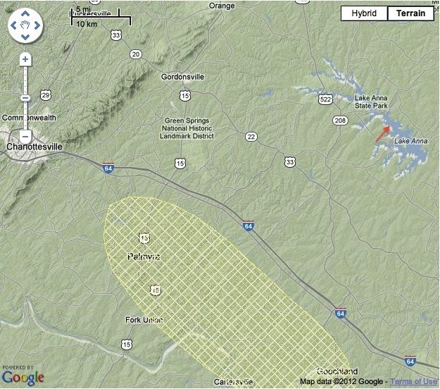
About five months later, the August 23 Virginia Earthquake precipitated the emergency shutdown of the two pressurized light water reactors at North Anna Nuclear Power Station (NPS) roughly 35 miles from my home. According to the U.S. Geological Service, the station is located at a distance of only 8 miles from the quake's epicenter and 20 miles from a quaternary fault zone. Seismologist Dr. James Martin of Virginia Tech. gave a comprehensive interview on the quake to Beverly Amsler aired on WVTF Radio IQ's Evening Edition for Nov. 22, 2011. The events made me wonder what a radiological emergency similar to that in Japan would entail in the U.S.

Area of quaternary faults and liquefaction in less than 15,000 years (hatched; source: USGS). The arrow points at the location of North Anna NPS. The epicenter of last Summer's Virginia quake was located near the junction between state routes 22 and 208.

When a utility company applies to the U.S. Nuclear Regulatory Commission (NRC) for the license to build a nuclear power reactor, an emergency plan for the eventuality of a radiological accident must be submitted. The plan must conform to federal regulations (10 CFR § 50.47 Emergency Plans). Dominion, the operator of North Anna NPS, is planning to construct a third unit on the station's premises and has hence developed such plan.

Examining Dominion's "North Anna 3 Combined License Application, Part 5: Emergency Plan, Revision 0 November 2007", reveals that much of the responsibility for the immediate decisions to be taken in the course of a severe reactor accident rests with the station operator, that is, primarily on the shoulders of the station's Emergency Coordinator (page II-1 of the proposed emergency plan). This person is instructed to collect information about the radioactive contamination monitored in the surroundings of the station, estimate the source term, that is the amount of radioactivity released from the failed reactor, determine the prevailing winds and precipitation, dispersing the radioactive matter, and constantly keep the relevant local, state and federal agencies up to date about the evolution of the accident.

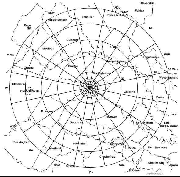
Map showing county lines and distance radii of Emergency Planning Zones proposed for North Anna NPS Unit 3 (source: Fig. I-2; Dominion).

Precise recommendations to the public depend on the source term and the progression of the plume in which the radioactivity is dispersed. The anticipated immediate protection measures are contingent mainly upon the distance from the power station. Radii of action are drawn (see drawing above). In addition to the protection of station personel (site emergency), the greatest concern lies with the safety of residents living within a 10-mile radius around the station, for whom precise instructions for health protection, evacuation and shelter have been planned (general emergency). This area is designated as the Plume Exposure Pathway Emergency Planning Zone. Radio stations periodically test emergency alert announcements (texts and further details can be found in the Commonwealth of Virginia Emergency Alert System Plan). Sirens alert residents to tune into local radio and TV stations for detailed announcements. Residents living within the 2 mile perimeter around the stricken NPS and within 5 miles straight downwind, including a margin on both sides (keyhole pattern), will be asked to evacuate immediately. Other residents within the 10-mile perimeter will be asked to stay indoors (NRC Backgrounder on Emergency Preparedness at Nuclear Power Plants).

The plans for residents beyond 10 miles depend on the amount and the duration of the release of radioactive matter from the reactor. The 50-mile radius encompasses the largest territory taken into consideration in the station's emergency plan. This area is designated as the Ingestion Exposure Pathway Emergency Planning Zone. Dominion set up a series of monitoring stations around the station. Near-real time ionizing radiation measurements available to the public within 100 miles from North Anna NPS, are disseminated by only two Radnet stations: one in Richmond and one in Harrisonburg, Virginia.

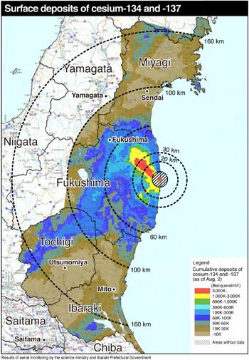
The color-coded map shows the magnitude of the fallout of cesium-134 and cesium-137, two major radioisotopes released after the severe nuclear reactor accidents at Fukushima Dai-ichi NPS in March last year. The deposits were mapped at the beginning of August, 2011. Radii are superimposed for orientation. Note, the plume's impression in red and yellow (source: MEXT).

Local wind and precipitation mainly dictate the shape of the plume in which the radioactivity is transported and disperses. To provide an example the color-coded radiation map above shows the overland plume-shaped radioactivity dispersal reconstructed with computer models from radiation monitor recordings after last year's severe accidents at Fukushima Dai-ichi NPS.

Average prevalence of wind directions at Louisa County Airport, Virginia, compiled from data collected between 1999 and 2011 (source: weatherspark.com).

In a hypothetical release at North Anna NPS resembling that of Fukushima, local weather conditions could produce a similar plume heading in a different direction. Wind speed and direction recorded at Louisa County Airport (see above) a few miles from North Anna NPS suggest that prevalent local winds blow on average from South/Southwest to North/Northeast. The plume would most likely progress toward Northern Virginia. Dispersal to the South toward the Richmond Metropolitan Area represents the second most probable direction.

The distance over which the plume eventually extends depends on the amounts of radioactivity released, the altitude of the release, wind speeds affecting the release, and precipitation. In Japan, the plume barely impacted Fukushima City, 35 miles from the nuclear reactor accidents. Note, however, that prevailing winds blew much of the airborne radioactive material out to sea.
Dominion's proposed emergency plan is most concerned with immediate impact after a severe radiological emergency. The long-term evolution of a wide-spread radioactive contamination can only be extrapolated from experiences after the Tchernobyl reactor disaster in 1986 and the ongoing contamination and clean-up around Fukushima Dai-ichi NPS. Regardless of the uncertainties, it seems only prudent to consult our local Radiological Emergency Plan, if we live within the 50-mile ingestion zone around a nuclear power station.

Acknowledgement
I thank the members of the simplyinfo.org discussion group for their cogent input, without which this post would not have been possible.

Relevant Sources

Friday, April 13, 2012

The Value of RadNet Ionizing Radiation Detection

In this post, I discuss uses of ionizing radiation measurements made available to the public by the U.S. Environmental Protection Agency's RadNet stations. In particular, I examine the usefulness of RadNet data for the early detection of radioactive fallout from distant radiological emergencies. As example, I use the reactor accidents at the Fukushima Daiichi Nuclear Power Station in the wake of the Mar. 11, 2011, Tōhoku-chihō Taiheiyō Oki Earthquake and Tsunami.

Iodine-131 and cesium-137 are prominent radioisotopes released after severe nuclear reactor accidents with fuel meltdowns. The decay of these isotopes produces a mix of beta and gamma radiation. The gamma radiation is emitted when the atomic nuclei transmute through intermittent energy states at isotope-specific energies.
Near-real time air filter gamma gross count rates measured in nine energy ranges at the RadNet station in Harrisonburg, Virginia (courtesy EPA). Because of the disparate values, the count rates are scaled logarithmically on the ordinate, compressing the peaks at high count rates. 
I used air filter measurements from the RadNet station in Harrisonburg, Virginia. The EPA publishes graphs of hourly gamma radiation gross count rates in nine energy ranges (see graph above).

Gamma spectrum of iodine-131 (Arena, 1971). Counts/channel are plotted on a logarithmic scale versus energy [keV]. Peaks are labelled in MeV.
Iodine-131 with a physical half-life of 8.05 days and an effective half-life in the whole body of 7.6 days possesses its greatest energy peak at 360 keV, a second-ranking peak at 280 keV, a third peak at 638 keV and a fourth peak at 724 keV (Arena, 1971). The lower couple fall into range 3 (200-400 keV) , whereas the higher couple fall into range 5 (600-800 keV) in the RadNet graph.

Gamma spectrum of cesium-137 (Arena, 1971). Counts/channel are plotted on a logarithmic scale versus energy [keV]. Peaks are labelled in MeV
By contrast, cesium-137 with a physical half-life of 30.17 years and an effective half-life in the whole body of 70 days emits gamma radiation at 662 keV, falling into range 5 of the RadNet graph. However, backscatter (Compton effect), that is low-energy detector counts produced by incomplete energy transfer between the ionizing radiation and the detector material, contributes a considerable fraction of the total count rate to range 3. Although the precise shape of the spectral curves shown above depends on the radioactivity of the sources and the instruments used for the measurement, the energy peaks remain invariable and representative. Therefore, the spectra may can be employed for the demonstration of principles.

Partial integration of the areas under the spectral curves taking the logarithmic scale of the counts/channel into account suggests that the iodine-131 decay contributes about 91 percent of the total count rate summed over both ranges to range 3, whereas cesium-137 decay will contribute about one third to this range. Therefore, if both isotopes are present in the sample, the count rate measured in range 3 does not exclusively reflect iodine-131 decay, and iodine-131 will also contribute to the count rate measured in range 5, though to a smaller degree than cesium-137. Despite this cross-contamination, a prominent increase in range 3 suggests the presence of iodine-131 and in range 5 that of cesium-137. Furthermore, the EPA provides offline post-hoc data for identified radioisotopes.

Regardless of its low spectral resolution, the real-time RadNet graph may potentially have its uses for the identification of a radiological incident. An increase above the average counts per minute (CPM) measured in ranges 3 and 5 beyond three standard errors of the mean can be considered statistically significant with 95 percent confidence. Mean count rates measured in the past can be queried in the RadNet database. Sequences of up to 400 measurements can be downloaded in a batch.

To determine mean count rates for the two energy ranges of interest, that is ranges 3 and 5, I chose the period between Feb. 22 and Mar. 10, 2011, and subsequently compared the means averaged over this epoch to the count rates observed in the same epoch this years. Radioactive decay adheres to the Poisson distribution in which the standard error is equal to the square root of the mean count rate. If the current count rate exceeds the mean by three standard errors, the probability of the increase being random is less than five percent.
Graph of gamma gross count rates measured in nine energy ranges taken from air filter samples at the RadNet Station in Harrisonburg, Virginia. The bottom lines of the red boxes indicate three standard errors above the mean count rate of the same epoch a year ago.
The graph above shows that this year's count rates statistically significantly exceeded the mean in the examined time window on roughly a handful of occasions. However, most comprise all energy ranges except 9 (magenta). If increases were only detected in range 3 (blue), we would most likely be confronted with a statistically significant presence of iodine-131. By contrast, a statistically significant increase in ranges 3 (blue) and 5 (yellow) would most likely indicate the presence of cesium-137.

Concomitant increases in gross beta count rates would further affirm the conclusions above, because both radioisotopes also emit beta radiation. Note, however, that the above assertions are purely based on statistical probability and causal inference. Great care must be taken to establish reasonable cause.

Iodine-131 and cesium-137 can be distinguished with time, using the difference in physical half-life between the two isotopes. Iodine-131's half-life is at 8.05 days considerably shorter than that of cesium-137 at 30.17 years. Following a pulse release of both isotopes into the atmosphere, iodine-131 should mainly contribute to the count rates measured early after the release. When the samples are remeasured ten half-lives later, that is after 80 days, the contribution of iodine-131 to the count rate will have diminished to one-thousandth. By contrast, the contribution of cesium-137 with its 30-year half-life is going to persist. Therefore, if repeated measurements of the same sample ascertain a decline in count rate commensurate with iodine-131's half-life, the radioisotope was present in the sample, and the remainder ought to be cesium-137.

Though the RadNet measurements may not immediately lend themselves to the distinction between iodine-131 and cesium-137, they may prove useful for the detection of radioactive fallout from a distant radiological accident. To test this idea, I tapped into the data collected at Harrisonburg in the weeks after the catastrophic nuclear reactor failures at the Fukushima Daiichi Nuclear Power Station situated on the shores of the Pacific Ocean 160 miles north of Tokyo in early March last year, that is between Mar. 12 and Mar. 28, 2011.

The station's reactors incurred loss of cooling in the wake of a magnitude-9 earthquake on Mar. 11, 2011, followed by 15-meter high tsunami waves inundating the structures (TEPCO press release with the title "Analysis and evaluation of the operation record and accident record of Fukushima Daiichi Nuclear Power Station at the time of Tohoku-Chihou-Taiheiyou-Oki-Earthquake," dated May 23, 2011). The nuclear fuel in three operating reactors melted down, producing great amounts of hydrogen. Between Mar. 12 and Mar. 15, hydrogen that had accumulated in the reactor buildings triggered massive explosions devastating the top floors of the structures and releasing vast amounts of radioactive matter into the atmosphere.

The first unit, Unit 1, exploded in the early afternoon of Mar. 12. The second unit, Unit 3, exploded two days later, and the third unit, Unit 4, though it was shutdown for inspection at the time, incurred an explosion in the early morning of Mar. 15. The reactor building of Unit 2, which was operating, suffered minor visible damage. However, since Unit 2's fuel melted, radioactivity was released from this reactor as well.

 Gross count rates from air filter samples collected at Harrisonburg, Virginia, over roughly two weeks after the first radioactive release from Fukushima.
Iodine-131 and cesium-137 were prominent in the airborne releases from the damaged reactors. The graph above depicts the gamma gross count rates collected in nine energy ranges at Harrisonburg over roughly two weeks after the first radioactive release from Fukushima, the statistical significance thresholds (dashed black lines) in ranges 3 (dark blue line) and 5 (yellow line), as well as the gross beta count rate (dashed red line). Peaks of significant gamma gross rate increases are evident in almost all energy ranges. None was confined exclusively to ranges 3 and 5. The light-blue line above the abscissa indicates the period in which the Fukushima Daiichi Nuclear Power Station incurred hydrogen explosions.

March 14 was the first day after the Fukushima Daiichi Nuclear Power Station began to release vast amounts of radioactivity, on which Harrisonburg registered significant peaks in gamma ranges 3 and 5 concomitant with an increase in beta gross count rate (dashed red line). A second such coincidence followed on Mar. 15. Then a triplet of coincident peaks followed on March 17, 19 and 20 (light blue dots above the abscissa). Because the peaks are spaced in about the same time intervals as the three hydrogen explosions at the Fukushima Daiichi Nuclear Power Station, this triplet of peaks represents the most probable harbinger of the arrival of fallout from Fukushima in Virginia, suggesting that radioactive airborne particulate from Fukushima reached Harrisonburg in five days.

The suggested time of arrival is a day ahead of that predicted by the cesium-137 dispersion model of Winiarek and others (2011) at the Centre d'Enseignement et de Recherche en Environnement Atmosphérique (CEREA), Marne la Vallée, France, and two days in advance of that of the iodine-131 dispersion modeled by Wotawa (2011) at the Zentralanstalt für Meteorologie und Geodynamik (ZAMG), Vienna, Austria.

Global iodine-131 dispersion after the Fukushima reactor accidents, 2011, according to the simulation model by Wotawa (2011), ZAMG, Vienna, Austria. 

Taking the above findings together, RadNet air filter count rate measurements seem to provide superb sensitivity for the detection of minute traces of airborne radioactive material, permitting us to identify distant radiological accidents half ways around the globe, if examined in proper factual context. Certainly, RadNet stations represent potent tools capable of alerting us to fallout from radiological accidents closer to home.

References

Monday, March 19, 2012

Project X-12: Borst's Imaginary Nuclear Locomotive

After half-a-century experience with the commercial use of nuclear power, it may seem difficult to conceive the sustainability of a nuclear-powered train engine.

In 1954, however, Professor Lyle B. Borst and his colleagues at the University of Utah pursued a concept for a locomotive powered by a nuclear reactor. Babcock & Wilcox Co. co-designed the reactor in a private venture. The project was dubbed X-12 and attracted the interest of five railroad companies, nine manufacturers, and the international media [1,2]. The locomotive was projected to cost 1.2 million dollars in 1954, double the price of four contemporary diesel units coupled together to produce the same horse powers.

Artist's rendering of the proposed X-12 nuclear powered locomotive from a 1954 hobby article [1] (a - air compressor for brakes; b - 24 driving wheels in six-wheeled trucks; c - engine platform; d - heavy-duty bridge truss supporting the reactor's weight; e - 600 hp electric motors; f - nuclear reactor; g - two of four main generators; h - two-chambered shielding; i - main steam turbine; j - pivoted articulation; k - piping connecting condenser and chiller bank; l - chiller bank; m - trailing truck; n - fans blowing air over radiators for cooling; o - reactor containment; p - condenser; q - gear box; r - electrical cabinet; s - engineer; t - regulator/throttle; u - brake; v - fireman;).
Operating on only 14 kg liquid fuel, the locomotive was envisaged to span 58 meters in length and muster 7,000 horse powers, rivaling the remarkably strong Ae 8/8 electric locomotives of the Swiss BLS Railway of the same epoch. These double units with Bo'Bo'+Bo'Bo' wheelbase (UIC classification) were only half that long.
Ae 8/8 near Kandersteg, Berne, Switzerland (courtesy: Klaus Kort).
Though, the X-12 would theoretically reach 60 miles/h in breath-taking 3 minutes and 32 seconds, pulling a 5,000-ton train, the nuclear locomotive would have weighed 360 tons. The reactor's radiation shielding mustered 200 tons alone. By contrast, the whole afore-mentioned electric Ae 8/8 weighs roughly as much as the shielding of the X-12 (180 metric tons).

The X-12's stream-lined body emulated the diesel locomotive design of the 1950s [1,2]. The two-sectioned behemoth was to consist of a 38-meter long engine, with a cab up front and the power plant behind, plus a 20-meter long 'tender' carrying the radiators for cooling turbine steam. The assembly was conceived to rest on an articulated platform riding on a (Co'Co')(Co'Co')(4) wheelbase (UIC classification).

The power plant was to consist of the nuclear reactor, the main steam turbine for power generation as well as steam condensers and chillers. A gear box coupled the turbine shaft to four electric generators.

The unavoidable massive radiation shielding called for small components in the engine room. At a rotor shaft length of only 120 inches and a diameter of only 24 inches, the team accomplished to design powerful space-saving generators that, despite their small size, could cope with the demands of the twelve 600-horsepower electric motors driving 24 wheels.

Further accommodating the limited space available, the engine's reactor was to possess a peculiar design. The reactor core was to be filled with liquid uranium oxide dissolved in sulphuric acid, providing greater symmetry for neutron fluxes at smaller neutron loss than the other popular, less efficient designs that used solid fuel packed into rods [3].
Borst's reactor schema shown in his patent [3] (2 - transverse section on line 2-2; 10 - fuel chamber; 12 - cylindrical pressure wall; 18 - coolant tubes; 24 - recombiner; 26 - external steam separator; 28 - riser; 30 - downcomer; 32 - vapor outlet line; 34 - coolant pump; 36 - suction line; 38 - coolant inlet chamber line; 45 - primary shield; 46 - fuel circulation baffles; 47 - u-shaped primary shield wall; 49 - primary shield roof; 50 - turbine; 51 - catalyst; 52 - liquid fuel surface; 53 - recombiner condenser; 54 - recombiner condenser discharge line; 55 - recombiner condenser feedwater line; 56 - recombined water return line; 58 - emergency cooling heat transfer tube; 60 - inlet header of emergency cooling heat transfer tube; 62 - outlet header of emergency cooling heat transfer tube; 64 - control rod;).
Furthermore, the heat transfer from a homogeneous liquid core is superior to that of a heterogeneous core consisting of rods because of the rod cladding and the uneven coolant flow among the rods. These advantages lend themselves particularly to small nuclear reactors that must produce high energy output. The Nobel Prize-laureates Eugene Wigner and Enrico Fermi developed the original reactor, known as aqueous homogeneous reactor (AHR), in the 1940s as an intermediate step to thorium reactors (Hargraves and Moir, 2011[4]). A circulating solution of 242 liters uranyl sulphate, a yellow-green salt, served as fuel [4].

The fuel core of the X-12's reactor was supposed to measure only 36 inches in diameter and 10 inches deep. The reactor pressure vessel, clad in an eight-inch steel primary shield, was made to fit into the 13 x 13 x 9 feet cavity of a secondary fluid-tight shield, also made of eight inch steel, encompassing the middle section of the engine and measuring 15 by 15 by 10 feet on the outside. The space between the two shields was to be filled with high viscosity hydrocarbon fluid to absorb internal motion on accidental impact and a hydrogenous shielding material to absorb more radiation.

The reactor consisted of a cylindrical reactor pressure vessel, shorter than wide, in which a steam-driven pump force-circulates the core's fluid, representing the primary coolant circulation for nuclear fission heat transfer. For secondary cooling, roughly 10,000 ¼-inch stainless steel tubes, traversing the core, join an inlet and an outlet chamber attached to each end of the reactor pressure vessel. The water-filled chambers, covering a large part of the reactor core surface, were thought to double as coolers and neutron reflectors, diminishing the escape of neutrons from the core. Coolant pumped through the tube and chamber system feeds steam to the main turbine. An additional coolant loop circulates through the chiller banks in the tender, cooling the turbine's exhaust steam in the main condenser.

As in any nuclear power plant, the water presumably needed to be filtered for contaminants before reuse, its chemistry needed to be balanced, and some water would be lost in the process. The engine could not do without filter beds and a make-up tank.

At full power, the engine's reactor would produce 30,000 kW thermal. Despite, the fuel in the reactor pressure vessel was not going to exceed 240 ℃ (460 ℉) at 4.5 MPa (megaPascal) gauge and, therefore, would not boil. The secondary cooling water would reach 207 ℃ (405 ℉) at 1.7 MPa gauge. These values are low compared with pressurized light water reactor (PWR) widely used in contemporary commercial nuclear power plants. That design must harness water temperatures of up to 315 ℃ (600 ℉) at 15.5 MPa.

Because of the intense radiation, however, almost half the solvent would dissociate into hydrogen and oxygen (radiolysis) within 13 minutes. Hence, the liberated hydrogen needed to be continuously recombined with the oxygen in a catalytic platinum recombiner/condenser installed above the pressure vessel. The recovered water could subsequently be returned into the core.

The liquid fuel concept allowed short-lived, neutron flux-hampering, volatile fission products to simply bubble out of the core fluid, and elegantly combined neutron moderation and efficient heat transfer. In addition, spent fuel could be exchanged without opening the reactor pressure vessel, posing a crucial handling advantage, because the reactor would have needed refueling every two to four months.

We may wonder whether the locomotive would have proved safe to operate. Borst and his colleagues hardened the reactor components to withstand collisions in an effort to prevent radiation releases and fuel spills. The reactor control rods, mounted at 60 degree angle, possessed shear points that would break on impact at accelerations equal to or above 0.2 g, lowering the rods into the core and scramming the reactor. Coolant forced through a subset of tubes traversing the core was supposed to help remove the resulting decay heat from the core in such emergency shutdown.

Professor Borst argued that ultimately the benefit versus cost of fuel compared with other sources of energy would decide the X-12's future. In order to sustain a chain reaction, most nuclear fuel used in commercial applications consists of uranium-238 enriched with the more fissile uranium-235 beyond its natural prevalence of 0.7 percent. In commercial light water nuclear power reactors burning solid uranium oxide, the enrichment is in the order of 3.5 percent. By contrast, Prof. Borst intended to run his reactor with weapon-grade highly enriched uranium, that is uranium-238 enriched with uranium-235 to more than 85 percent. In fact, his patent application called for 7 kg pure uranium-235. At today's DOE prices, one filling of fuel for the locomotive would cost 104 million dollars.

The fission products of uranium-235 mainly comprise radioactive isotopes of barium, cesium, iodine, strontium, and xenon, of which the highly volatile iodine-131, with a half-life of 8 days, and barium-140, with a half-life of 13 days, pose an immediate health hazard, when released into the environment. Accidental releases of cesium-137 and strontium-90 with half-lives of about 30 years are of long-term concern. Professor Borst mentions little about the enormous expenses to provide radiation safety during fuel handling and maintenance, and eventually the decommissioning of highly radioactive components at the end of the reactors' life span. Moreover, reprocessing of used nuclear fuel has been wrought with unresolved technological pitfalls to date, and endstorage sites where highly radioactive waste can be safely and indefinitely stored remain elusive in the U.S.

Three scores ago, the advent of nuclear power's commercial use was greeted with exuberant enthusiasm, promising a future of limitless energy and boundless applications. Despite the optimism, Prof. Borst's idea of a mobile reactor must have been met with skepticism from its conception. A prototype X-12 locomotive never gained traction as much as we know, probably because of the enormous investments already involved in the development of the engine alone.

It seems certain that cost weighed on the minds of the railroad company executives as heavily as the X-12 might have weighed on the tracks. Without substantial government subsidies, particularly for highly purified uranium-235, the railroad companies could not have run such locomotive cost-effectively. Liability insurance would have been enormous. I counted a dozen major U.S. train wrecks in 2011 alone. Moreover, safety and security of the use of nuclear-powered train engines would pose daunting challenges to homeland security today.

Confronted with what arguably must have seemed insurmountable obstacles from the project's conception, Borst and the University of Utah appeared in no particular hurry to obtain approval for a patent [3]. The parties applied in 1955. The application was eventually approved in 1964, consuming almost a decade. At best, the X-12 may add an illustrious conversation piece to a model railroad today.

References
  1. "Auf Bahnsteig 3 - Atom-D-Zug", hobby, July 7, 1954.
  2. "The atomic locomotive. A physics professor's practical dream, the massive X-12 could run for months on a charge of U-235." Life, Jun 21, 1954.
  3. Borst LB (1964) Nuclear reactor for a railway vehicle. U.S. Patent № 3,127,321.
  4. Hargraves R, Moir R (2011) Liquid Fuel Nuclear Reactors. American Physical Society Forum on Physics & Society.

Wednesday, February 15, 2012

Fukushima: Fuel Meltdowns & Cold Shutdown

Cold shutdown of an intact nuclear reactor, also known as mode 4 (see Risk Assessment of Operational Events Volume 4 – Shutdown Events, Revision 1.0, April 2011), essentially denotes the state in which the water in the reactor pressure vessel can be maintained below boiling at atmospheric pressure without the constant need of adding water to the closed-loop cooling system. The operator of the Fukushima Dai-ichi Nuclear Power Station severely damaged by the Tohoku Earthquake and Tsunami last March, Tokyo Power and Electric Co. (TEPCO), maintains that the three reactors the fuel core of which melted down have reached cold shutdown last autumn.

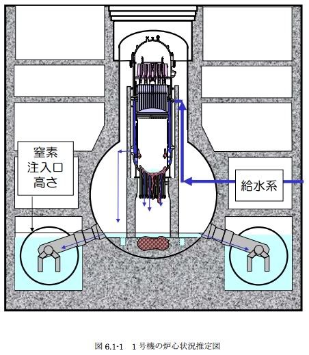
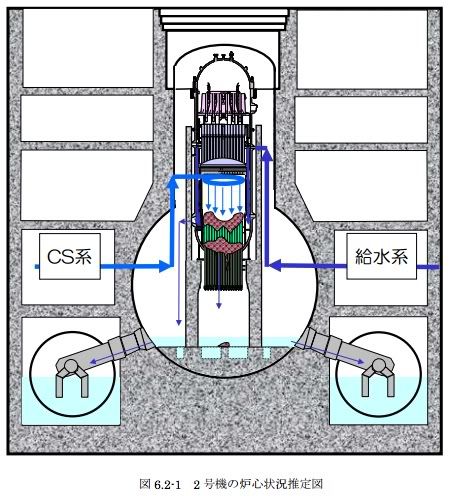
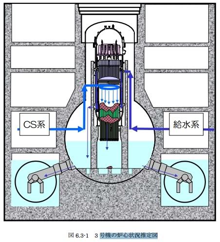
The three reactors were in operation at the time of the quake, which triggered seismic SCRAMs, precipitating emergency shutdowns. In its report with the title "Unit 1-3 core about the state of Fukushima Daiichi Nuclear Power Station" dated Nov. 30, 2011, TEPCO examines the fuel core meltdowns in the stricken reactors. The company summarizes its synopsis on the state of the reactor cores in the schemas shown in order from Unit 1 to Unit 3 below. The schemas deserve close inspection.
Attention must be paid to the location of the corium, that is the molten fuel rods, and the water levels in each reactor. Corium melted through the reactor pressure vessels of the three reactors. The reactor pressure vessels are enclosed in primary containments consisting of a pear-shaped drywell connected to a ring-shaped, partially water-filled suppression chamber also known as wetwell.
The fuel core of the oldest reactor, Unit 1, melted down most, slumping to the reactor pressure vessel's bottom, burning through its steel and into the 10 meter-thick concrete floor of the drywell below. In the other units, most melted fuel presumably resides inside the reactor pressure vessels, and only small amounts are believed to have reached the drywell floor.
The heat from radioactive decay in the corium must be continuously cooled to confine corium flow and avoid a fuel geometry potentially conducive to re-criticality. Hence, TEPCO has been pumping water into the reactor pressure vessels through feedwater and core sprayer (CS) lines at rates ranging from roughly 4 (Unit 1) to 18 m3/h (Unit 2). Paths of the injected water vary among the reactors and flow rates have been altered between paths. Regardless, considering a reactor vessel volume of 400 cubic meters and more, it would take days to fill the vessels at the total flows TEPCO administers.

Despite the water injections, no reactor pressure vessel is completely filled. Water needs constantly supplied to prevent boil off. At Unit 1, some water seems to collect at the bottom of the reactor pressure vessel. Most water, however, appears to leak via the drywell into the wetwell, which is almost completely filled. Unit 2 shows no water in the reactor pressure vessel, more in the drywell, and less in the wetwell. At Unit 3, the water also seems to pass entirely through the reactor pressure vessel, filling drywell and wetwell to the highest level observed. Eventually, water leaking from the three reactors wends its way into the turbine building basements from which TEPCO pumps it through newly constructed filter systems for decontamination back into the reactor pressure vessels. The precise leak paths from the reactors remain unknown.

TEPCO reports reactor temperatures regularly. The measurements are based on thermostats that were originally installed at various strategic locations around the reactor vessels, and may have been damaged during the course of the accident. Verification of sensor functionality is difficult. Repair or replacement is impossible to date because of high radiation. Therefore, the reported temperatures must be taken with a grain of salt. Moreover, location and state of the molten fuel can only be inferred from indirect observation.

By contrast, cold shutdown implies water temperature control with precise and accurate knowledge of the reactor parameters and may not entirely pertain to the situation at Fukushima Dai-ichi Nuclear Power Station. The water TEPCO injects through the feedwater line mostly flows down the reactor pressure vessel's inside wall, whereas the water injected through the core sprayer irrigates the center where the fuel core used to be located.

Consistent with the company's hypothesis that most molten fuel in Unit 2 accumulated at the center of the reactor pressure vessel's bottom, TEPCO increased the flow of the core sprayer and reduced the flow through the feedwater orifice about two weeks ago, apparently in the hope of cooling the core melt at the center more effectively (TEPCO press release with the title "Plant Status of Fukushima Daiichi Nuclear Power Station (as of 3:00 pm, February 14)"). The result was a dramatic increase in temperature above the boiling point measured at one of three locations at the bottom of the reactor pressure vessel. The temperature kept rising until the thermostat failed. Reversing the water flow pattern was to no avail. Only doubling the total flow rate seemed to help.

TEPCO investigated the possibility of renewed nuclear fission, searching for radioactive fission products in air and water samples with nuclear decay energy spectrometry, and concluded that no re-criticality occurred (TEPCO press release with the title "Plant Status of Fukushima Daiichi Nuclear Power Station (as of 3:00 pm, February 15)"). Regardless, the fragility of water temperature control in Unit 2's reactor suggests that it is quite possible that much water the company injects bypasses a substantial portion of the molten fuel and only cools the reactor pressure vessel.
This is the most likely scenario!

Addenda

  • TEPCO released this video on Jan. 20, 2012. The video was captured with an endoscopic camera inside the primary containment of Fukushima Daiichi Nuclear Power Station Unit 2. This is TEPCO's first visit inside the primary containment of a reactor with a fuel meltdown. Extreme levels of radiation cause the color pixel artifacts. Note water raining from above intensely and persistently, the reddish-brown corrosion on the containment's inside wall and piping, and no standing water anywhere in view of the camera (02/19/2012).
  • In today's report with the title "Result of the second investigation inside of Primary Containment Vessels, Unit 2, Fukushima Daiichi Nuclear Power Plant," TEPCO released its findings from a second endoscopic exploration of Unit 2's primary containment vessel with improved equipment. In addition to the first exploration's findings, TEPCO discovered water standing roughly 60 cm deep at the bottom of the drywell. The water temperature was about 50 ℃; 40 ℃ were measured in the air at higher elevations. These observations suggest that the drywell bottom around the pedestal room does not seem to be leaking. Information of the conditions inside the pedestal room is lacking. This room is located directly under the reactor pressure vessel (RPV) and may contain the melted fuel that escaped the RPV. Its doors are normally sealed. Regardless, water TEPCO constantly pumps into the RPV seems to wend its way into the drywell from which it flows into the suppression chamber through the pipes connecting the two. The chamber must have sprung leaks through which the inflowing water seeps into the reactor building's basement (03/26/2012).
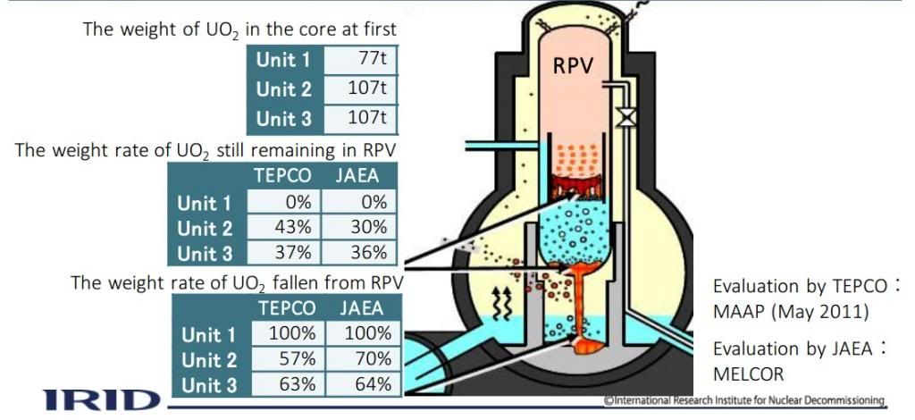
  • The diagram below shows TEPCO's and the Japan Atomic Energy Agency's most recent estimates of the fractions of melted-down fuel residing inside and outside each unit's reactor pressure vessel (RPV). Note, all of unit 1's fuel is presumed to have relocated to the pedestal room below the vessel (05/21/2014).
(source: International Research Institute for Nuclear Decommissioning)


Acknowledgement
I thank the contributors of SimplyInfo.org without whose help I could not have written this post.