Showing posts with label Daiichi. Show all posts

Wednesday, November 20, 2013

Fukushima: Gaseous Effluent Handling & Hydrogen Explosions

In my last post with the title "Why Fukushima's Reactors Failed" published online Nov. 4, 2013, I used the 2011 Fukushima Daiichi Nuclear Power Station disaster to emphasize the existential importance of housing cooling water pumps and electric power equipment essential for emergency reactor shutdowns in flood-resistant buildings, particularly for power stations located in flood-prone areas.

Elaborating on a comment to that post, this essay will point out that exhaust stack elevation could have made a crucial difference in the Fukushima reactor accidents.

Electric motor-driven fans support just about every air handling system in the reactor building of a nuclear power station (see the numerous blower symbols in Fig. 1 from Row, 1971), pumping effluent gases to the main exhaust stack and maintaining a negative building pressure that disallows potentially contaminated air to escape unfiltered into the environment.  Contaminated effluents are forced through filters and vented through the main exhaust stacks, except for hardened venting. During hardened venting, contaminated steam and gases may directly be routed to the exhaust stacks as a means of last resort  in an emergency, relieving pressure from the reactor after all other options have been exhausted. Furthermore, hardened venting may prevent hydrogen produced by melting fuel rod cladding and radiolysis from reaching explosive concentrations.

Bird's eye view of Fukushima Daiichi Nuclear Power Station after hydrogen explosions destroyed the service floors of units 1 (left), 3 and 4. The tall exhaust stack towers can be seen on the left between units 1 and 2 and at center between units 3 and 4. The small sheds housing the fan gear are located at the base of the towers (source: cyptome.org).

But, the tall exhaust stacks at Fukushima need fan-support to generate sufficient draft. The fan gear is housed in small shed at their base. During a station blackout, the stacks must rely on draft alone.

According to the Fukushima Nuclear Accident Report (Interim Report) Dec. 2, 2011, of the stricken power station's operator Tokyo Electric Power Company (TEPCO), hardened venting released hydrogen in Unit 1's reactor building, flowing back through open valves and baffles. When mixed with air at concentrations above four percent, hydrogen may explosively deflagrate and detonate. At Unit 3, the hydrogen may have exploded inside the primary containment vessel.

Explosion at units 1 and 4 (courtesy: Goddard's Journal).
By contrast, Unit 4 had been shutdown for inspection at the time of the earthquake, the reactor had been unloaded, and the fuel had been stored in its spent fuel pool. Despite, the reactor incurred a hydrogen explosion during the night after the violent explosion at Unit 3. It appears unlikely that the hydrogen sustaining Unit 4's explosion was produced there.

Junction of SGTS effluent piping of Unit 3 and Unit 4 at the base of shared stack (arrow) (source: TEPCO).
TEPCO contents that hydrogen migrated from Unit 3 to Unit 4 through the Standby Gas Treatment System, or SGTS for short (see lower center of schema in Fig. 1). The SGTS is used to filter contaminated air and funnel it to the main exhaust stack. According to TEPCO, gas from Unit 3's SGTS was permitted to cross over into the piping of Unit 4's SGTS at the junction connecting both systems to the shared stack.

Unit 4's SGTS filter contamination. The connection to the stack shared with Unit 3 is on the right (source: TEPCO).
TEPCO supports this contention with finding progressively greater outside-in contamination of the filter cascade of Unit 4's SGTS.

Had the shared exhaust stacks been tall enough to passively generate sufficient draft, the hydrogen explosions may have been prevented, particularly the one at Unit 4. Therefore, it is prudent to ensure that all nuclear power stations are outfitted with exhaust stacks tall enough to provide sufficient draft when all power fails.

Tomorrow, Nov. 21, 2013, the US Senate Committee on Environment and Public Works and the Subcommittee on Clean Air and Nuclear Safety will hold a joint hearing on the "NRC's Implementation of the Fukushima Near-Term Task Force Recommendations and other Actions to Enhance and Maintain Nuclear Safety."

Hopefully, the NRC has incorporated sufficient exhaust stack elevation into its recommendations for US reactor operators.

Reference
  • Row TH (1973) Radioactive waste systems and radioactive effluents. Georgia Institute of Technology Short Course.
Acknowledgement
SimpyInfo.org provided the information for this post.

Monday, November 4, 2013

Why Fukushima's Reactors Failed

Bird's eye view of Fukushima Daiichi Nuclear Power Station before the earthquake and tsunami on Fri. Mar. 11, 2011. Units 1 (right) to 4 (left) are seen in the foreground and 5 (left) and 6 (right) further back. Units 1, 2 and 3 incurred fuel meltdowns (source: TEPCO).

Three of the six reactors at Fukushima Daiichi Nuclear Power Station 120 miles north of Tokyo on Honshu's east coast incurred nuclear fuel meltdowns after the 2011 Tōhoku Earthquake and Tsunami. One reactor had been defueled for inspection. The station's two other reactors could be shutdown safely.

Bird's eye view of Fukushima Daini Nuclear Power Station before the earthquake and tsunami on Fri. Mar. 11, 2011 (unit 1 is on the right). All units could be safely shutdown. (source: TEPCO).

The four operating reactors at Fukushima Daini Nuclear Power Station seven miles away could also be saved.

The meltdowns at Daiichi led to powerful hydrogen explosions, releasing amounts of radioactive material over land and sea only rivaled by the 1986 Chernobyl reactor disaster in the Ukraine. The government imposed an exclusion zone around the stricken station, because radiation doses were deemed too high for habitation. To date, roughly 70,000 former residents cannot return home permanently. According to Shigeru Sato, Tsuyoshi Inajima, Monami Yui and Emi Urabe's report with the title "Japan Mulls Plan for One Operator to Run All Reactors: Energy" published by Bloomberg Oct. 22, 2013, cleanup and compensation are currently projected to cost 112 billion dollars, roughly equaling the cost for two Hurricane Sandies.

A multitude of inquiries have attempted to uncover the causes underlying the Fukushima accident. The operator of both power stations, Tokyo Electric Power Company, tells us what happened in its accident reports. The company's fact compilation points to one essential lynchpin: the residual heat removal system must not fail.

The reactors at Daiichi and Daini are boiling water reactors with General Electric's Mark I or Mark II primary containment systems.
Schematic of a boiling water reactor with a Mark I containment(source: IAEA).
The Mark I containments consist of a pear-shaped drywell housing the reactor pressure vessel and a doughnut-shaped wetwell, also known as torus or pressure suppression chamber, holding a large pool of water. The drywell is connected at the bottom to the wetwell with equally spaced radial vent pipes.

Schematic of a boiling water reactor with a Mark II containment(source: IAEA).
The Mark II containments are shaped differently, but still consist of a drywell with the reactor vessel and a wetwell with a pressure suppression pool.

When nuclear reactors need shutdown in an emergency, control and safety rods are inserted between the fuel rods in milliseconds, disrupting the nuclear chain reaction. Furthermore, the reactor pressure vessel's main steam lines may be isolated from the power-generating turbine and main condenser when potential damage to the pipes is anticipated. Without heat transfer, decay heat builds in the reactor pressure vessel, revving up pressure. Water must be injected into the vessel as coolant and to keep the fuel covered to prevent a meltdown.

Though emergency pumps can inject water into the vessel at high pressure, the pressure must be relieved to prevent damage to the vessel and to facilitate greater coolant injection. Safety relief valves are periodically opened to depressurize the vessel. The valves discharge high-pressure steam into the wetwell's pool, in which the steam is condensed and the pressure is absorbed. If the vessel was breached and high pressure steam bursted into the drywell, the pressure would be relieved into the suppression pool through the pipes that directly connect the drywell to the wetwell.

At Fukushima Daiichi Nuclear Power Station, the quake vibrations tripped the operating reactors automatically. Control and safety rods were inserted and the pressure vessels were isolated. Access to outside power was lost because of quake damage. Emergency diesel generators started up to provide power.

About 40 minutes later, tsunami waves flooded power distribution panels and emergency generators located low in the reactor turbine buildings. Battery banks continued to power emergency core cooling systems. Except for Unit 1 which is equipped with a isolation condenser, two reactor steam-driven pumps, the reactor core isolation cooling system and the high pressure coolant injection system, were available to inject water into the reactor pressure vessels, initially from storage tanks and later from the wetwell pools, while the operators attempted to depressurize the reactors, relieving steam into the pools.

  • Eyewitness account of a Daiichi operator:
    “We went into the field in order to open the vent valves. When we were at the near the torus (that is, the wetwell, ed.) room, we heard a large, weird popping sound. The valve is at up high, so I put my foot on the torus to lift myself up. Then, my black rubber boot was melted like butter [source: TEPCO interim report, Dec 2, 2011, page 53].”
  • "The decomposition of the rubber-sulphur compound (that is, vulcanized rubber, ed.) takes place to an appreciable extent at the usual temperatures of vulcanization [source: Bureau of Standards Journal of Research, Volume 4 (1930), page 512]."
  • "A typical vulcanization temperature for a passenger tire is 10 minutes at 170 °C [source: Vulcanization]."

However, once the pool temperature exceeds 100 °C, absorption of reactor pressure becomes progressively less effective. The steam-driven pumps sucking water from the pool stop working above that temperature. Therefore, removing heat from the wetwell pool is absolutely necessary.

Schematic showing the residual heat removal system on the right (source: NRC).
The residual heat removal system fulfills this function. It consists of electric motor-driven pumps that flush cold service water from a large body of water, known as ultimate heat sink, through heat exchangers, cooling the wetwell pool. In Fukushima, the ocean is the ultimate heat sink, and the seawater pumps of the residual heat removal system were built near the water’s edge 4 meters above sea level.
Exposed seawater pumps at Fukushima Daiichi Nuclear Power Station 2011 (source: Daisuke Tsuda). 
At Daiichi the pumps stood exposed on the dock and the tsunami rendered them irreparable, except one that could be re-powered and jury-rigged to supply units 5 and 6.

By contrast, at Daini the pumps were housed in buildings that can be seen dockside in the areal view above. The structures were not flood resistant, but withstood the brunt of the debris-laden waves. The pump for unit 3 persevered without loss of function, and the others could be repaired before the reactor fuel was uncovered. All reactors at both power stations with functioning residual heat removal systems could be shutdown safely within days.

Therefore, electric power must be available and the residual heat removal system must remain operable for nuclear reactors of the Fukushima type to successfully complete an emergency shutdown. These conditions impose a major constraint on accident recovery, representing a fundamental weakness of the reactor design. The residual heat removal system must remain operable under the conditions of flooding and station blackout.

Thirty reactors of this type currently operate in the United States. A number are sited in flood-prone areas. A moratorium should be imposed on these reactors, until the operators can ascertain that service water pumps are protected against inundation, debris, and loss of power.

Related Posts

Thursday, July 18, 2013

No Cold Shutdown at Fukushima

Steam detected emanating from the refueling floor of Fukushima Dai-ichi Nuclear Power Station Unit 3 in July 2013 (source: TEPCO).
According to Hiroko Tabuchi's post with the headline "Steam Detected at Damaged Fukushima Reactor" published by The New York Times today, the operator of the stricken Fukushima Dai-ichi Nuclear Power Station Tokyo Electric Power Company (TEPCO) noticed steam emanating from the exposed refueling floor of Unit 3, the nuclear fuel of which melted down in the wake of the 2011 Great Tōhoku Earthquake and Tsunami and which was severely damaged by a violent hydrogen explosion.

As I discussed in my essay with the title "Fukushima: Fuel Meltdowns & Cold Shutdowns" posted Feb. 15, 2012, TEPCO assumed having reached temperatures below the boiling point of water, that is 100 °C, 17 months ago, using an improvised open-loop cooling water cycle (see IAEA news by Peter Kaiser with the title "Cold Shutdown Conditions Declared at Fukushima" dated Dec. 18, 2011). Reaching reactor pressure vessel temperatures below the boiling point of water with closed cooling water cycles after the shutdown of an intact nuclear reactor is known as cold shutdown, a mode TEPCO proclaimed to have achieved at the time.

TEPCO speculates the steam detected this week is generated by rainwater seeping into the reactor (see TEPCO's press release in Japanese dated Jul. 18, 2013).

Regardless of the source, steam emanating from the primary containment vessel implies that temperatures inside the vessel must be 100 °C or higher. The discovery of new steam proves the company's assertion of cold shutdown incorrect. TEPCO is preparing countermeasures for the possibility of a nuclear chain reaction. Follow the latest developments on simplyinfo.org.

 Related Posts

Friday, September 28, 2012

Fukushima Daiichi Nuclear Power Station Unit 1: Blunt Force Impact Damage Inside Primary Containment

The Mar. 11, 2011, Tohoku-Chihou-Taiheiyou-Oki Earthquake and Tsunami precipitated losses of coolant and fuel meltdowns in three reactors at Fukushima Daiichi Nuclear Power Station. Unit 1 was the station's first to incur a meltdown.

Yesterday, the nuclear power station's operator Tokyo Electric Power Co. (TEPCO) released a video of the first endoscopic exploration inside Unit 1's primary containment vessel (PCV) (TEPCO press release with the title "Punching an Access Hole at the Penetration (X100B Penetration) of Unit 1 PCV at Fukushima Daiichi Nuclear Power Station", dated Sep. 27, 2012). TEPCO's video can be downloaded here. General Electric's Mark I primary containment systems are composed of a pear-shaped drywell housing the reactor pressure vessel (RPV) and a doughnut-shaped, water-filled suppression chamber, also known as wetwell. TEPCO's video below explores the inside of the drywell (courtesy: SimplyInfo.org).


Note that the upper part of the drywell is filled with dense steam. Water must be boiling at the bottom of the primary containment.

Furthermore, the dominant color of the drywell's inner surface is grimy black and not brown as observed in Unit 2 (see the video in my post with the title "Fukushima: Fuel Meltdowns & Cold Shutdown" published online Feb. 15, 2012), indicating combustion either by explosion or fire.

18:05 minutes into the video blunt force impact on the drywell becomes visible. A large piece of sharp-edged debris can be seen deposited adjacent to exposed rebar of a reinforced concrete wall structure. The impact suggests that the location was struck by a heavy object, perhaps the object nearby, either falling from above or projected against the drywell wall like a missile.

A high-pressure steam jet exiting from a small RPV breach, also known as small breach Loss of Cooling Accident (LOCA), could have blasted chunks off the RPV or its piping, turning the chunks into projectiles that impacted the drywell.
Addendum
  • During the past week, TEPCO undertook another video camera foray into the primary containment vessel (PCV) of Unit 1 (TEPCO's press handout with the title "Investigation Results of the Inside of Unit 1 PCV at Fukushima Daiichi Nuclear Power Station" dated Oct. 15, 2012). The company released three videos of the exploration.
    The two pictures below, courtesy of Simplyinfo.org, were captured between 37 and 44 minutes in the hour-long video.


    The pictures show three types of damage: • the PCV floor fractured (first picture; top left corner), • scattered metal shards (both pictures), suggesting piping shattered in a blast caused by excess interior pressure, and • extreme force impact fragmented large structures and components (bottom picture)(10/17/2012).

Sunday, July 1, 2012

Fukushima: Station Black Out & Delusion

According to a Japan Times editorial with the title "Nuclear power plant collusion" published online Jun. 23, 2012, industry and government experts appointed by the Japanese Nuclear Safety Commission in 1991 to revise safety standards for station blackouts (SBO) concluded in 1993
“that even if an SBO occurs, it would not lead to a severe accident."
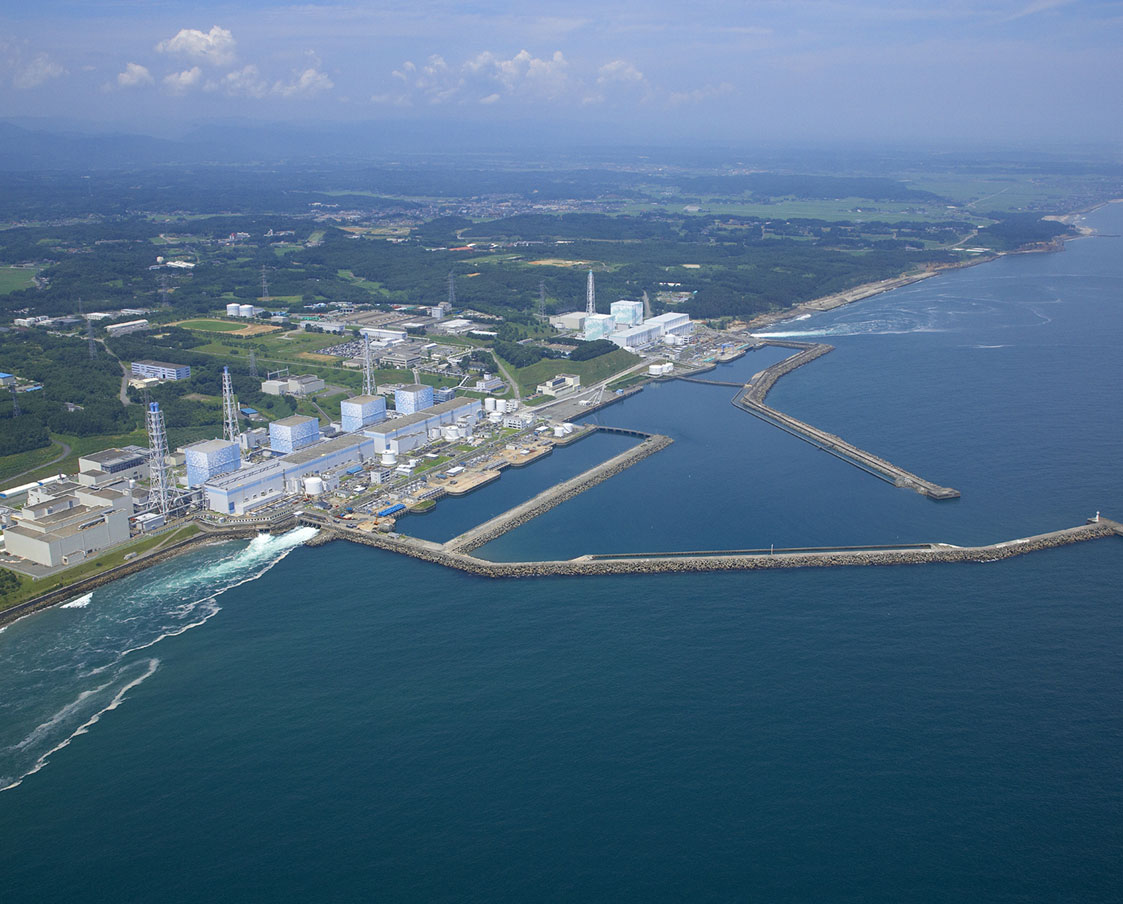
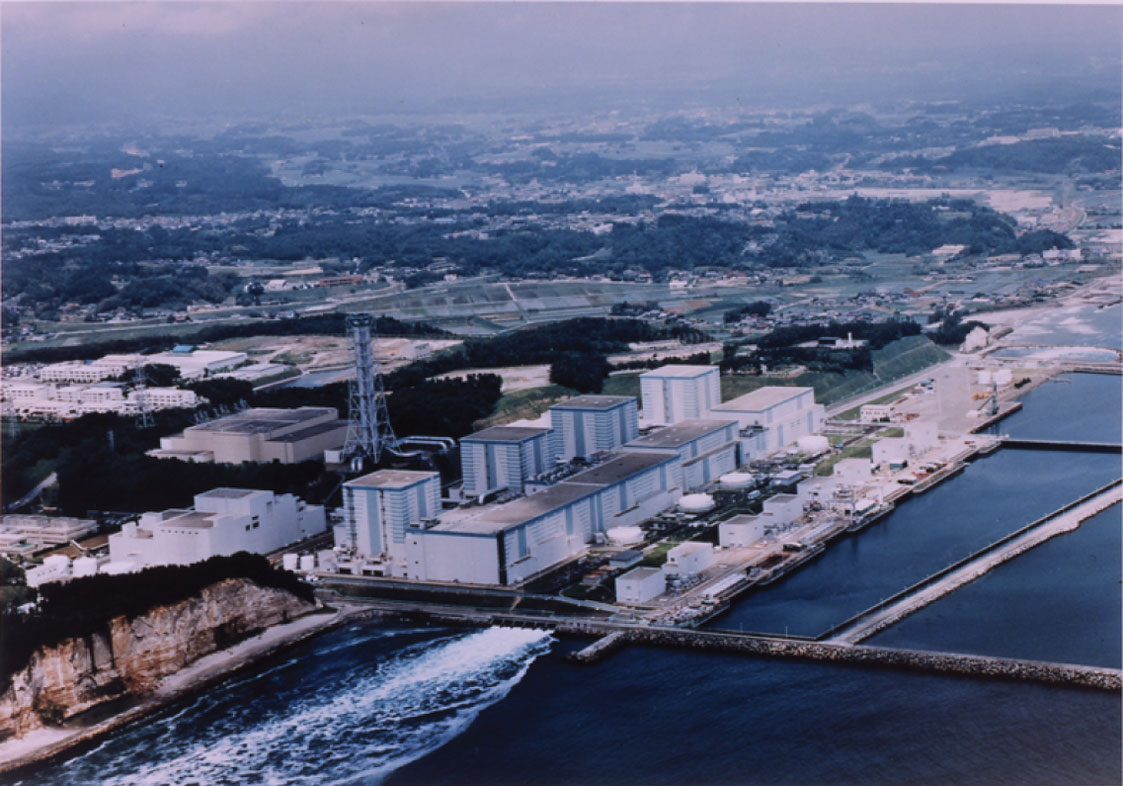
Last year's nuclear reactor disaster at Fukushima Dai-ichi Nuclear Power Station (NPS) in the wake of the great Tohoku-Chihou-Taiheiyou-Oki Earthquake and Tsunami can be considered a station blackout that developed into a severe nuclear accident.

According to Cook and others (1981), “a station blackout is defined as the complete loss of all AC (alternating current, ed.) electrical power to the essential and nonessential switchgear buses in a nuclear power plant.” The authors examined a hypothetical station blackout (SBO) and its consequences, using the boiling water reactor (BWR) at Brown's Ferry NPS Unit 1 as model. The unit produces 1152 MW electrical power, and its design resembles closely that of units 1 - 4 at Fukushima Dai-ichi NPS, except Unit 1 at Fukushima was not equipped with an automatic depressurization system and had an isolation condenser instead of a reactor core isolation cooling (RCIC) system. The description of events at Fukushima Dai-ichi NPS on the day of the earthquake provided in this essay is based on the information the station's operator Tokyo Electric Power Company (TEPCO) has released since the accident.

In the study of Cook and others (1981), the loss of offsite AC power trips the main turbine, scrams the reactor, and the emergency diesel generators fail. Battery-supplied DC power continues to support emergency shutdown systems and components important to reactor safety. The authors explore with models various possible event paths after the batteries are exhausted. Though ground motion rather than a loss of power scrammed the reactors at Fukushima Dai-ichi NPS automatically, the authors' predictions on the worst accident progression converge on the chain of events at Fukushima after 4 p.m. on Mar. 11, 2011. Below, Unit 1 at Fukushima Dai-ichi NPS is used as example.

Systems, Structures, and Components Important to Safety
In conjunction with a high pressure coolant injection (HPCI) system, with which all reactors at Fukushima Dai-ichi as well as at Brown's Ferry are outfitted, RCIC system and isolation condenser constitute crucial components designed to keep the nuclear fuel in the reactor pressure vessel (RPV) covered with water, when the electrical power-generating turbine trips, the main steam isolation valves close, and the reactor scrams. HPCI and RCIC system are described in detail in the appendix of the study of Cook and others (1981).

In a scram, all safety control rods are inserted into the fuel core, instantly disrupting the nuclear chain reaction. The closing of the main steam isolation valves disconnects the reactor from the turbine, and the decay heat that the fuel produces cannot be transferred to the main steam condenser. Alternating current is no longer produced onsite. Other sources must supply power needed to operate the reactor. The offsite electrical grid represents the primary alternative source, and should the grid fail, emergency diesel generators are held in reserve onsite. If the emergency generators fail, battery-supplied direct current (DC) is supposed to support important instrumentation and valves for several hours.


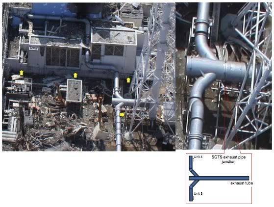
Schema of the isolation condenser at Fukushima Dai-ichi NPS Unit 1, labeled here 'emergency steam condenser.' Note subsystem A and subsystem B are both fed by one coolant supply line. The coolant in the condenser is evaporated, while cooling reactor pressure vessel (RPV) steam. The coolant vapor is vented directly into the environment via a pair of exhaust pipes on the west wall of the reactor building. MO - manual-remote actuated motor operated valves (TEPCO).

The isolation condenser at Fukushima Dai-ichi Unit 1 consists of two identical subsystems of water-cooled heat exchangers designed to reduce reactor pressure vessel (RPV) temperature and pressure by steam condensation. The condensate is returned to the RPV to help keep the fuel covered. Similar to Brown's Ferry Unit 1, however, when the RPV's safety/relief valves open to protect the vessel from overpressure, large volumes of steam escape. The valves lift automatically when a pressure setpoint is reached, but can also be actuated remote-manually from the control room with battery-supplied DC power and compressed air. As a result, the water level falls.

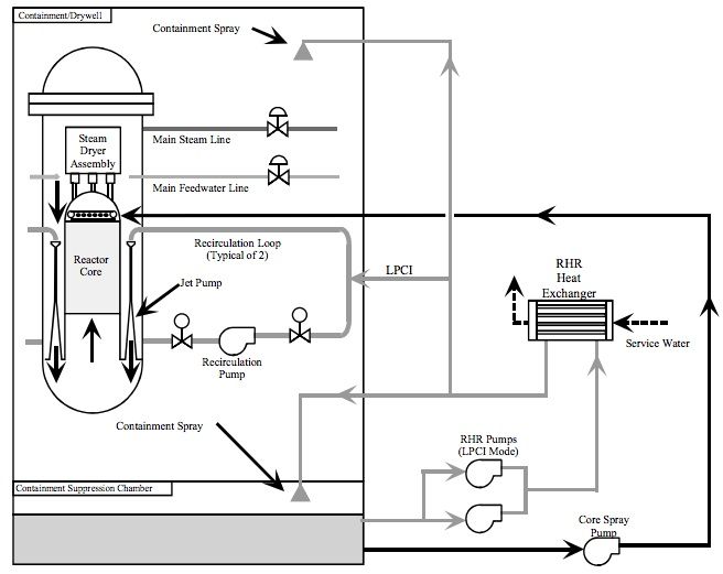
Schema of the high pressure coolant injection (HPCI) system at Fukushima Dai-ichi NPS Unit 1. MO - motor operated, HO - hand operated, and AO - air operated valves. Note the reactor steam-driven turbine that powers pump and booster pump. The feedwater for the reactor pressure vessel (RPV) is alternatively provided by the condensate storage tank or the wetwell (suppression chamber) pool (TEPCO).

Low water level automatically starts the high pressure coolant injection (HPCI) system, a reactor steam-driven pump, which can inject coolant rapidly at high pressure into the RPV, keeping the fuel core covered.

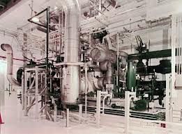
HPCI system with reactor steam turbine-driven pump (source: nuclear tourist).

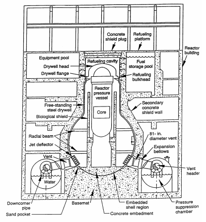
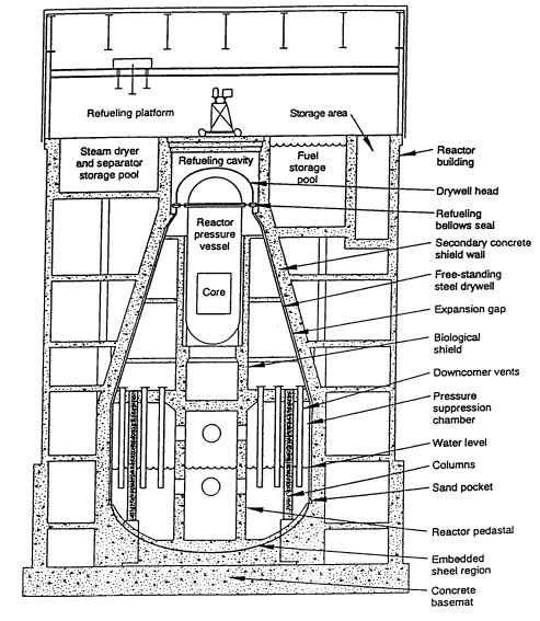
General Electric's Mark I primary containment system encloses the RPVs of units 1-5 at Fukushima Dai-ichi NPS. The system consists of a pear-shaped drywell, housing the RPV, connected with large-diameter pipes like spokes to a hub to a doughnut-shaped water-filled wetwell, also known as suppression chamber. The pipes are designed to relieve pressure building up in the drywell into the wetwell. By contrast, the safety/relief valves relieve RPV pressure into the wetwell through separate smaller diameter pipes.
Schema of the Mark I containment system inside the reactor building of Fukushima Dai-ichi Unit 1. Note the pear-shaped drywell, housing the reactor pressure vessel, connected with 81-inch pipes to the doughnut-shaped wetwell, also known as suppression chamber, filled halfway with water (courtesy: Simplyinfo.org).

The drywell is designed to operate safely up to 138 °C (Cook and others, 1981). When the fuel core in the RPV is uncovered, the core temperature will rise above 1,300 °C, the fuel rods will begin to melt, RPV penetration seals begin to leak, and ambient temperature in the drywell will heat to more than 149 °C, or 300 °F. Above this temperature, valve control solenoids, electrical cable insulation and electrical penetration module seals fail.

Hundreds of kilograms hydrogen are produced at the damaged fuel rods after fuel uncovery, when the super-heated zirconium oxide cladding of the fuel rods reacts with steam. Once the RPV is breached, the hydrogen and gaseous radioactive fission products will escape into the drywell. Once the drywell seals deteriorate in the heat, the gases will vent into the reactor and turbine building. Hence, rising radiation dose rates in these buildings suggest that a fuel meltdown is in progress.

Timeline
☢ 14:46, the earthquake strikes tripping operating units 1, 2 and 3. Offsite AC power service is lost. The emergency diesel generators start up. Two generators supply Unit 1 (TEPCO press release with the title "Release of the Fukushima Nuclear Accidents Investigation Report" dated Jun. 20, 2012).
☢15:27 and ☢15:35, tsunami waves inundate the generator rooms of units 1 to 5. The diesel generators for Unit 1 trip. In the control room wedged between the reactor and the turbine building, charge indicators flash for a brief moment. Alarms ring out and die. The tsunami also floods DC power distribution panels. In rapid succession, control room illumination, displays, indicators, gauges, annunciators and controls dim. On the ground floor below, water stands 80 cm deep.
☢15:30, the RPV pressure recorder for Unit 1 stops. Minutes later, the RPV temperature recorders halt.
☢15:37, control room crew call SBO for units 1 and 2. The government is notified. Crew arriving from the basement of the turbine building confirm that the emergency diesel generators failed and the corridor lights are out.
☢15:50, all DC power is lost. The operators are left with emergency lights on the Unit 1 side of the control room, and in total darkness on the Unit 2 side, unable to read vital reactor parameters and observe the results of their interventions. Unit 1's isolation condenser status is rendered indeterminable. The status indicator for the HPCI system is turned off. The system has fallen into a non-bootable state. The RPV water level displays cease.
☢16:15, the water level recorders for Unit 1 stop.
☢16:25, the shift supervisor declares the status of the emergency core cooling system and the RPV parameters unobtainable.
☢17:56, preparations begin for fire pumps to inject water into Unit 1's RPV.
☢20:07, crew is able to collect gauge readings in the reactor building for the first time since the SBO's inception, concluding the fuel was covered and RPV pressure held at 6.9 MPa.
☢20:47, some control room power is restored with a portable generator. Auxiliary batteries are connected to the electrical RPV water level displays, re-establishing monitoring capability at 21:19.

The observed RPV water level on the gauge indicated less than a foot above the fuel and may have been underestimated by several feet, because the reference leg of the water level gauge, also known as Yarway gauge, is located in the drywell. The reference leg is needed to account for vessel pressure and temperature. The drywell was progressively heating up, evaporating water in the gauge's reference leg and producing lower than actual water levels, when the drywell temperature exceeded design basis (Hodge and others, 1992).

Emergency Cooling
☢14:52, both subsystems of Unit 1's isolation condenser started automatically. Control room crew notes a drop in RPV pressure believed commensurate with the rapid diminution of temperature attributed to the isolation condenser activation.
☢15:03, in compliance with instructions, an operator closes valves of the isolation condenser loop. According to manual, the rate of change in RPV temperature was not permitted to be greater than 55 ℃/h because of the risk of RPV failure.

Line valves were opened to enable HPCI. The control room crew initially found no indication that Unit 1's HPCI system was inoperable. They reassured themselves that the HPCI system was ready to inject water into the RPV, should the safety/relief valves actuate automatically, that is 7.4 MPa for lifting and 6.9 MPa for reseating, resulting in a drop of RPV water level below the threshold and starting HPCI. However, because the RPV water level seemed to persist at sufficiently high levels, keeping the fuel covered, and pressure remained below safety/relief valve lift point, HPCI was not expected to start before the tsunami struck and was disabled afterwards.

The crew continued to control RPV pressure remote-manually with isolation condenser subsystem A into the next day, intermittently opening and closing the steam line valves. TEPCO believes that the isolation condenser was effective in avoiding an excessive rise in RPV pressure, because no evidence has been found that safety/relief valves lifted.

It is important to note that depressurizing the RPV with the help of the safety/relief valves, while adding sufficient coolant with the isolation condenser or the HPCI system, would have been essential for avoiding an immediate fuel meltdown. The operators actuated safety/relief valves at Units 2 and 3, but not at Unit 1.

Simulations
In their SBO simulation study on a BWR-4 boiling water reactor, Park and Ahn (2012) assume that battery power will be available for 6 hours. RCIC and HPCI systems are working, but begin to fail, once the batteries are exhausted. Under these conditions, the author's simulation suggests that, without operator intervention, core uncovery and melt will begin 8 and 9 hours into the SBO, respectively. The drywell will fail after 18 hours. TEPCO's simulation assumes that the drywell temperature beyond which leakage begins is crossed 13 hours into the SBO.

By contrast, the almost concomitant loss of AC and DC power at Fukushima accelerated the progression of events. TEPCO estimates that Unit 1's fuel core began to uncover already about 2 hours into the SBO ("Analysis and evaluation of the operation record and accident record of Fukushima Daiichi Nuclear Power Station at the time of Tohoku-Chihou-Taiheiyou-Oki-Earthquake", TEPCO, May 23, 2011).

Wilkie (2011) suggested that the fuel core in the reactor would uncover and begin to melt in slightly less than one hour, if HPCI, RCIC or the isolation condenser and safety/relief valves failed. Similarly, Cook and others (1981) predict that, without any power and without coolant injection into the RPV, fuel is uncovered in about half-an-hour, the core meltdown begins after two hours, and the drywell electrical penetration modules fail after 4.5 hours, venting radioactive noble gas, cesium, and iodine-based fission products into the reactor building (their Table 9.7.).

Furthermore, Cook and others (1981) conclude that the fuel would uncover twice as rapidly, the fuel rods would begin to melt within less than one hour, and the drywell would begin to vent about 20 minutes earlier, that is within a little more than four hours into the SBO, if a loss of coolant through a small breach in the RPV occurred, also known as small-breach LOCA (loss of coolant accident). The breach could consist of a stuck-open safety/relief valve or a hole in the reactor pressure vessel 13.8 cm in diameter.

Lochbaum (2011) suspected a LOCA might have happened, but could not find any evidence in the data TEPCO released at the time of his evaluation. In accord, Tanaka (2011) hypothesized a LOCA as part of the accident progression of Unit 1, and TEPCO's simulations match the reactor data best, when a LOCA is assumed. Below, I discuss events past 4 p.m. on March 11, 2011, that support the occurrence of a small-breach LOCA.

Small-Breach LOCA
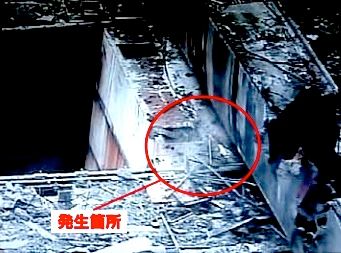
☢17:19 crew that had been sent to Unit 1's reactor building to check on the isolation condenser bilge water level ran into hazardous radiation dose rates at the building entrance, forcing them back ("Fukushima Nuclear Accident Analysis Report (Interim Report)," TEPCO, Dec. 2, 2011).
☢23:00, contamination had reached the turbine building. A reconnaissance team recorded 1.2 mSv/h in front of the north side ground floor airlock, which is roughly 20,000 times greater than the 50 nSv/h ordinarily detected on the premises.

The progressive increase in dose rate, already observed shortly after 5:00 p.m. and corroborated at further distance three hours later, suggests that a fuel meltdown was underway already at that time, consistent with a rapid severe accident development. Without cooling, the drywell must have overheated 90 minutes into the SBO, developed leaks, and allowed substantial radioactive gases to vent into the building, leading to the detected dose rate increases. While, no evidence of a massive RPV water loss has been presented to date, a small RPV breach therefore constitutes a probable cause that would explain fuel uncovery and meltdown within less than one hour.

To date, TEPCO has not reported that safety/relief valves were actuated. However, after the loss of power a valve could have failed open unnoticed. Hydrogen produced by the fuel rod cladding/water reaction may have accumulated in the piping. Deflagrating gas could have blown open a valve.

Certainly, we shall learn one day whether a small-breach LOCA occurred at Fukushima Dai-ichi NPS Unit 1. Without doubt, the meltdown at Unit 1 progressed more rapidly than initially believed. The remarkably narrow window of opportunity for operator intervention between station blackout and fuel meltdown should give all stakeholders pause.

Acknowledgement
I thank the contributors to Simplyinfo.org. This evaluation could not have been accomplished without their input.

Addendum
  • Today NHK WORLD aired a video report with the title “Nuclear Watch: Blind Spot in Nuclear Safety“, documenting that an air monitoring station 5.6 km from Fukushima Dai-ichi Nuclear Power Station registered a greater than anticipated spike in radiation on Saturday Mar. 12, 2011, after hardened venting at the station’s Unit 1 had commenced and before a hydrogen explosion damaged that unit. As the NHK WORLD report explains, hardened venting is supposed to reduce primary containment vessel pressure, filtering most radioactive contaminants out by passing the effluent through the primary containment vessel's suppression pool. TEPCO presumed that only 0.01 percent of the initial radioactivity would vent into the atmosphere. However, the radiation dose rates observed at the monitoring station were magnitudes greater than what they should have been according to TEPCO's presumption. NHK WORLD hypothesizes that the greater than expected radiation release resulted from an increase in suppression pool temperature, diminishing the pool's filtering capacity. In a model experiment, the release was increased 500-fold. NHK WORLD suggests that earlier gas and steam releases from the reactor pressure vessel heated the water in the pool via open safety relief valves. According to TEPCO’s reports to date no safety relief valves were opened at Unit 1. A LOCA releasing gas and steam from the reactor pressure vessel into the primary containment vessel represents an ever more likely possibility (04/30/2014).
References

Friday, April 13, 2012

The Value of RadNet Ionizing Radiation Detection

In this post, I discuss uses of ionizing radiation measurements made available to the public by the U.S. Environmental Protection Agency's RadNet stations. In particular, I examine the usefulness of RadNet data for the early detection of radioactive fallout from distant radiological emergencies. As example, I use the reactor accidents at the Fukushima Daiichi Nuclear Power Station in the wake of the Mar. 11, 2011, Tōhoku-chihō Taiheiyō Oki Earthquake and Tsunami.

Iodine-131 and cesium-137 are prominent radioisotopes released after severe nuclear reactor accidents with fuel meltdowns. The decay of these isotopes produces a mix of beta and gamma radiation. The gamma radiation is emitted when the atomic nuclei transmute through intermittent energy states at isotope-specific energies.
Near-real time air filter gamma gross count rates measured in nine energy ranges at the RadNet station in Harrisonburg, Virginia (courtesy EPA). Because of the disparate values, the count rates are scaled logarithmically on the ordinate, compressing the peaks at high count rates. 
I used air filter measurements from the RadNet station in Harrisonburg, Virginia. The EPA publishes graphs of hourly gamma radiation gross count rates in nine energy ranges (see graph above).

Gamma spectrum of iodine-131 (Arena, 1971). Counts/channel are plotted on a logarithmic scale versus energy [keV]. Peaks are labelled in MeV.
Iodine-131 with a physical half-life of 8.05 days and an effective half-life in the whole body of 7.6 days possesses its greatest energy peak at 360 keV, a second-ranking peak at 280 keV, a third peak at 638 keV and a fourth peak at 724 keV (Arena, 1971). The lower couple fall into range 3 (200-400 keV) , whereas the higher couple fall into range 5 (600-800 keV) in the RadNet graph.

Gamma spectrum of cesium-137 (Arena, 1971). Counts/channel are plotted on a logarithmic scale versus energy [keV]. Peaks are labelled in MeV
By contrast, cesium-137 with a physical half-life of 30.17 years and an effective half-life in the whole body of 70 days emits gamma radiation at 662 keV, falling into range 5 of the RadNet graph. However, backscatter (Compton effect), that is low-energy detector counts produced by incomplete energy transfer between the ionizing radiation and the detector material, contributes a considerable fraction of the total count rate to range 3. Although the precise shape of the spectral curves shown above depends on the radioactivity of the sources and the instruments used for the measurement, the energy peaks remain invariable and representative. Therefore, the spectra may can be employed for the demonstration of principles.

Partial integration of the areas under the spectral curves taking the logarithmic scale of the counts/channel into account suggests that the iodine-131 decay contributes about 91 percent of the total count rate summed over both ranges to range 3, whereas cesium-137 decay will contribute about one third to this range. Therefore, if both isotopes are present in the sample, the count rate measured in range 3 does not exclusively reflect iodine-131 decay, and iodine-131 will also contribute to the count rate measured in range 5, though to a smaller degree than cesium-137. Despite this cross-contamination, a prominent increase in range 3 suggests the presence of iodine-131 and in range 5 that of cesium-137. Furthermore, the EPA provides offline post-hoc data for identified radioisotopes.

Regardless of its low spectral resolution, the real-time RadNet graph may potentially have its uses for the identification of a radiological incident. An increase above the average counts per minute (CPM) measured in ranges 3 and 5 beyond three standard errors of the mean can be considered statistically significant with 95 percent confidence. Mean count rates measured in the past can be queried in the RadNet database. Sequences of up to 400 measurements can be downloaded in a batch.

To determine mean count rates for the two energy ranges of interest, that is ranges 3 and 5, I chose the period between Feb. 22 and Mar. 10, 2011, and subsequently compared the means averaged over this epoch to the count rates observed in the same epoch this years. Radioactive decay adheres to the Poisson distribution in which the standard error is equal to the square root of the mean count rate. If the current count rate exceeds the mean by three standard errors, the probability of the increase being random is less than five percent.
Graph of gamma gross count rates measured in nine energy ranges taken from air filter samples at the RadNet Station in Harrisonburg, Virginia. The bottom lines of the red boxes indicate three standard errors above the mean count rate of the same epoch a year ago.
The graph above shows that this year's count rates statistically significantly exceeded the mean in the examined time window on roughly a handful of occasions. However, most comprise all energy ranges except 9 (magenta). If increases were only detected in range 3 (blue), we would most likely be confronted with a statistically significant presence of iodine-131. By contrast, a statistically significant increase in ranges 3 (blue) and 5 (yellow) would most likely indicate the presence of cesium-137.

Concomitant increases in gross beta count rates would further affirm the conclusions above, because both radioisotopes also emit beta radiation. Note, however, that the above assertions are purely based on statistical probability and causal inference. Great care must be taken to establish reasonable cause.

Iodine-131 and cesium-137 can be distinguished with time, using the difference in physical half-life between the two isotopes. Iodine-131's half-life is at 8.05 days considerably shorter than that of cesium-137 at 30.17 years. Following a pulse release of both isotopes into the atmosphere, iodine-131 should mainly contribute to the count rates measured early after the release. When the samples are remeasured ten half-lives later, that is after 80 days, the contribution of iodine-131 to the count rate will have diminished to one-thousandth. By contrast, the contribution of cesium-137 with its 30-year half-life is going to persist. Therefore, if repeated measurements of the same sample ascertain a decline in count rate commensurate with iodine-131's half-life, the radioisotope was present in the sample, and the remainder ought to be cesium-137.

Though the RadNet measurements may not immediately lend themselves to the distinction between iodine-131 and cesium-137, they may prove useful for the detection of radioactive fallout from a distant radiological accident. To test this idea, I tapped into the data collected at Harrisonburg in the weeks after the catastrophic nuclear reactor failures at the Fukushima Daiichi Nuclear Power Station situated on the shores of the Pacific Ocean 160 miles north of Tokyo in early March last year, that is between Mar. 12 and Mar. 28, 2011.

The station's reactors incurred loss of cooling in the wake of a magnitude-9 earthquake on Mar. 11, 2011, followed by 15-meter high tsunami waves inundating the structures (TEPCO press release with the title "Analysis and evaluation of the operation record and accident record of Fukushima Daiichi Nuclear Power Station at the time of Tohoku-Chihou-Taiheiyou-Oki-Earthquake," dated May 23, 2011). The nuclear fuel in three operating reactors melted down, producing great amounts of hydrogen. Between Mar. 12 and Mar. 15, hydrogen that had accumulated in the reactor buildings triggered massive explosions devastating the top floors of the structures and releasing vast amounts of radioactive matter into the atmosphere.

The first unit, Unit 1, exploded in the early afternoon of Mar. 12. The second unit, Unit 3, exploded two days later, and the third unit, Unit 4, though it was shutdown for inspection at the time, incurred an explosion in the early morning of Mar. 15. The reactor building of Unit 2, which was operating, suffered minor visible damage. However, since Unit 2's fuel melted, radioactivity was released from this reactor as well.

 Gross count rates from air filter samples collected at Harrisonburg, Virginia, over roughly two weeks after the first radioactive release from Fukushima.
Iodine-131 and cesium-137 were prominent in the airborne releases from the damaged reactors. The graph above depicts the gamma gross count rates collected in nine energy ranges at Harrisonburg over roughly two weeks after the first radioactive release from Fukushima, the statistical significance thresholds (dashed black lines) in ranges 3 (dark blue line) and 5 (yellow line), as well as the gross beta count rate (dashed red line). Peaks of significant gamma gross rate increases are evident in almost all energy ranges. None was confined exclusively to ranges 3 and 5. The light-blue line above the abscissa indicates the period in which the Fukushima Daiichi Nuclear Power Station incurred hydrogen explosions.

March 14 was the first day after the Fukushima Daiichi Nuclear Power Station began to release vast amounts of radioactivity, on which Harrisonburg registered significant peaks in gamma ranges 3 and 5 concomitant with an increase in beta gross count rate (dashed red line). A second such coincidence followed on Mar. 15. Then a triplet of coincident peaks followed on March 17, 19 and 20 (light blue dots above the abscissa). Because the peaks are spaced in about the same time intervals as the three hydrogen explosions at the Fukushima Daiichi Nuclear Power Station, this triplet of peaks represents the most probable harbinger of the arrival of fallout from Fukushima in Virginia, suggesting that radioactive airborne particulate from Fukushima reached Harrisonburg in five days.

The suggested time of arrival is a day ahead of that predicted by the cesium-137 dispersion model of Winiarek and others (2011) at the Centre d'Enseignement et de Recherche en Environnement Atmosphérique (CEREA), Marne la Vallée, France, and two days in advance of that of the iodine-131 dispersion modeled by Wotawa (2011) at the Zentralanstalt für Meteorologie und Geodynamik (ZAMG), Vienna, Austria.

Global iodine-131 dispersion after the Fukushima reactor accidents, 2011, according to the simulation model by Wotawa (2011), ZAMG, Vienna, Austria. 

Taking the above findings together, RadNet air filter count rate measurements seem to provide superb sensitivity for the detection of minute traces of airborne radioactive material, permitting us to identify distant radiological accidents half ways around the globe, if examined in proper factual context. Certainly, RadNet stations represent potent tools capable of alerting us to fallout from radiological accidents closer to home.

References

Wednesday, February 15, 2012

Fukushima: Fuel Meltdowns & Cold Shutdown

Cold shutdown of an intact nuclear reactor, also known as mode 4 (see Risk Assessment of Operational Events Volume 4 – Shutdown Events, Revision 1.0, April 2011), essentially denotes the state in which the water in the reactor pressure vessel can be maintained below boiling at atmospheric pressure without the constant need of adding water to the closed-loop cooling system. The operator of the Fukushima Dai-ichi Nuclear Power Station severely damaged by the Tohoku Earthquake and Tsunami last March, Tokyo Power and Electric Co. (TEPCO), maintains that the three reactors the fuel core of which melted down have reached cold shutdown last autumn.

The three reactors were in operation at the time of the quake, which triggered seismic SCRAMs, precipitating emergency shutdowns. In its report with the title "Unit 1-3 core about the state of Fukushima Daiichi Nuclear Power Station" dated Nov. 30, 2011, TEPCO examines the fuel core meltdowns in the stricken reactors. The company summarizes its synopsis on the state of the reactor cores in the schemas shown in order from Unit 1 to Unit 3 below. The schemas deserve close inspection.
Attention must be paid to the location of the corium, that is the molten fuel rods, and the water levels in each reactor. Corium melted through the reactor pressure vessels of the three reactors. The reactor pressure vessels are enclosed in primary containments consisting of a pear-shaped drywell connected to a ring-shaped, partially water-filled suppression chamber also known as wetwell.
The fuel core of the oldest reactor, Unit 1, melted down most, slumping to the reactor pressure vessel's bottom, burning through its steel and into the 10 meter-thick concrete floor of the drywell below. In the other units, most melted fuel presumably resides inside the reactor pressure vessels, and only small amounts are believed to have reached the drywell floor.
The heat from radioactive decay in the corium must be continuously cooled to confine corium flow and avoid a fuel geometry potentially conducive to re-criticality. Hence, TEPCO has been pumping water into the reactor pressure vessels through feedwater and core sprayer (CS) lines at rates ranging from roughly 4 (Unit 1) to 18 m3/h (Unit 2). Paths of the injected water vary among the reactors and flow rates have been altered between paths. Regardless, considering a reactor vessel volume of 400 cubic meters and more, it would take days to fill the vessels at the total flows TEPCO administers.

Despite the water injections, no reactor pressure vessel is completely filled. Water needs constantly supplied to prevent boil off. At Unit 1, some water seems to collect at the bottom of the reactor pressure vessel. Most water, however, appears to leak via the drywell into the wetwell, which is almost completely filled. Unit 2 shows no water in the reactor pressure vessel, more in the drywell, and less in the wetwell. At Unit 3, the water also seems to pass entirely through the reactor pressure vessel, filling drywell and wetwell to the highest level observed. Eventually, water leaking from the three reactors wends its way into the turbine building basements from which TEPCO pumps it through newly constructed filter systems for decontamination back into the reactor pressure vessels. The precise leak paths from the reactors remain unknown.

TEPCO reports reactor temperatures regularly. The measurements are based on thermostats that were originally installed at various strategic locations around the reactor vessels, and may have been damaged during the course of the accident. Verification of sensor functionality is difficult. Repair or replacement is impossible to date because of high radiation. Therefore, the reported temperatures must be taken with a grain of salt. Moreover, location and state of the molten fuel can only be inferred from indirect observation.

By contrast, cold shutdown implies water temperature control with precise and accurate knowledge of the reactor parameters and may not entirely pertain to the situation at Fukushima Dai-ichi Nuclear Power Station. The water TEPCO injects through the feedwater line mostly flows down the reactor pressure vessel's inside wall, whereas the water injected through the core sprayer irrigates the center where the fuel core used to be located.

Consistent with the company's hypothesis that most molten fuel in Unit 2 accumulated at the center of the reactor pressure vessel's bottom, TEPCO increased the flow of the core sprayer and reduced the flow through the feedwater orifice about two weeks ago, apparently in the hope of cooling the core melt at the center more effectively (TEPCO press release with the title "Plant Status of Fukushima Daiichi Nuclear Power Station (as of 3:00 pm, February 14)"). The result was a dramatic increase in temperature above the boiling point measured at one of three locations at the bottom of the reactor pressure vessel. The temperature kept rising until the thermostat failed. Reversing the water flow pattern was to no avail. Only doubling the total flow rate seemed to help.

TEPCO investigated the possibility of renewed nuclear fission, searching for radioactive fission products in air and water samples with nuclear decay energy spectrometry, and concluded that no re-criticality occurred (TEPCO press release with the title "Plant Status of Fukushima Daiichi Nuclear Power Station (as of 3:00 pm, February 15)"). Regardless, the fragility of water temperature control in Unit 2's reactor suggests that it is quite possible that much water the company injects bypasses a substantial portion of the molten fuel and only cools the reactor pressure vessel.
This is the most likely scenario!

Addenda

  • TEPCO released this video on Jan. 20, 2012. The video was captured with an endoscopic camera inside the primary containment of Fukushima Daiichi Nuclear Power Station Unit 2. This is TEPCO's first visit inside the primary containment of a reactor with a fuel meltdown. Extreme levels of radiation cause the color pixel artifacts. Note water raining from above intensely and persistently, the reddish-brown corrosion on the containment's inside wall and piping, and no standing water anywhere in view of the camera (02/19/2012).
  • In today's report with the title "Result of the second investigation inside of Primary Containment Vessels, Unit 2, Fukushima Daiichi Nuclear Power Plant," TEPCO released its findings from a second endoscopic exploration of Unit 2's primary containment vessel with improved equipment. In addition to the first exploration's findings, TEPCO discovered water standing roughly 60 cm deep at the bottom of the drywell. The water temperature was about 50 ℃; 40 ℃ were measured in the air at higher elevations. These observations suggest that the drywell bottom around the pedestal room does not seem to be leaking. Information of the conditions inside the pedestal room is lacking. This room is located directly under the reactor pressure vessel (RPV) and may contain the melted fuel that escaped the RPV. Its doors are normally sealed. Regardless, water TEPCO constantly pumps into the RPV seems to wend its way into the drywell from which it flows into the suppression chamber through the pipes connecting the two. The chamber must have sprung leaks through which the inflowing water seeps into the reactor building's basement (03/26/2012).
  • The diagram below shows TEPCO's and the Japan Atomic Energy Agency's most recent estimates of the fractions of melted-down fuel residing inside and outside each unit's reactor pressure vessel (RPV). Note, all of unit 1's fuel is presumed to have relocated to the pedestal room below the vessel (05/21/2014).
(source: International Research Institute for Nuclear Decommissioning)


Acknowledgement
I thank the contributors of SimplyInfo.org without whose help I could not have written this post.